Basic OSPF Lab

OSPF (Open Shortest Path First) is a type of link-state routing protocol used in computer networks. It allows routers to dynamically exchange information about the network topology, including the state and cost of each link. This information is used to calculate the shortest path to a destination network, making OSPF a reliable and efficient way to route traffic within a network. OSPF is commonly used in large enterprise networks and is known for its scalability, fast convergence times, and support for variable-length subnet masks.

OSPF is an interior gateway routing protocol (IGRP). That means that it’s a routing protocol used within an autonomous system (AS). OSPF uses Link State Advertisement (LSA) packets between routers running OSPF. LSAs are packets of information that routers exchange with one another in order to build and maintain a map of the network topology. Each router in an OSPF network generates its own set of LSAs, which describe the state and cost of each link to neighboring routers. These LSAs are flooded throughout the network, allowing all routers to build a complete picture of the network topology. By exchanging LSAs, OSPF routers are able to quickly and efficiently calculate the shortest path to a destination network, making OSPF a reliable and efficient routing protocol for large enterprise networks.

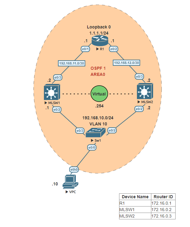
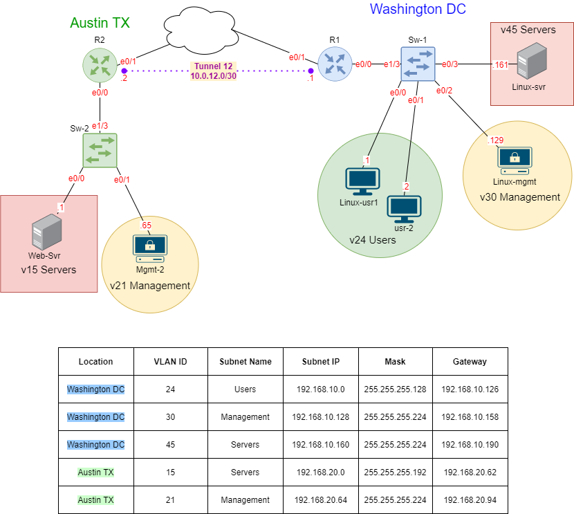
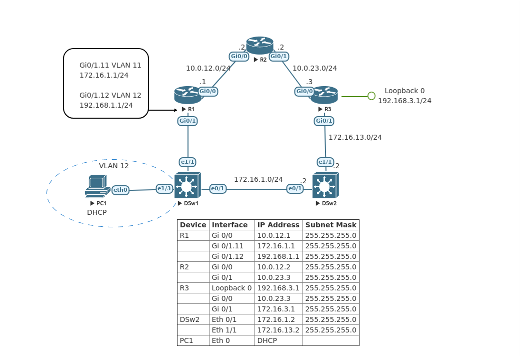
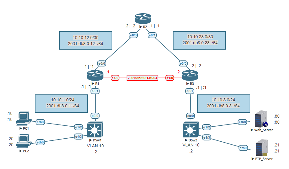
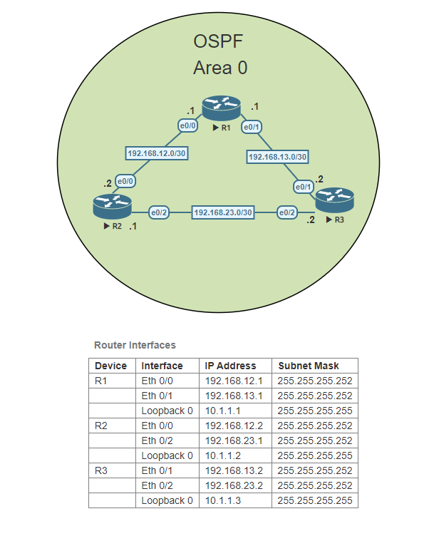
In this Lab, we will be configuring a basic OSPF topology using three routers in the same OSPF Area, Area 0. In OSPF, Area 0 is known as the backbone area of the network. It is the most important and central area in an OSPF network and is the only area that all other areas must connect to directly. The importance of Area 0 lies in its function as a transit area for routing information between different areas in the network. For this lab, we will concentrate only on OSPF Area 0. No other areas are needed.

Configure the hostnames on each Router

Access each router and configure the router hostname to match the topology above.

Router>enable
Router#configure terminal
Enter configuration commands, one per line.  End with CNTL/Z.
Router(config)#hostname R1
R1(config)#

Router>enable
Router#configure terminal
Enter configuration commands, one per line.  End with CNTL/Z.
Router(config)#hostname R2
R2(config)#

Router>enable
Router#configure terminal
Enter configuration commands, one per line.  End with CNTL/Z.
Router(config)#hostname R3
R3(config)#

Configure R1’s interfaces

Access R1 and configure each interface. Set a loopback address on loopback 0 to 10.1.1.1. Don’t forget to activate the interfaces.

R1(config)#interface ethernet 0/0
R1(config-if)#ip address 192.168.12.1 255.255.255.252
R1(config-if)#no shutdown
R1(config-if)#exit
R1(config)#interface ethernet 0/1
R1(config-if)#ip address 192.168.13.1 255.255.255.252
R1(config-if)#no shutdown
R1(config-if)#exit
R1(config)#interface loopback 0
R1(config-if)#ip address 10.1.1.1 255.255.255.255
R1(config-if)#exit
R1(config)#

Configure R2’s interfaces

Access R2 and configure each interface. Set a loopback address on loopback 0 to 10.1.1.2. Don’t forget to activate the interfaces.

R2(config)#interface ethernet 0/0
R2(config-if)#ip address 192.168.12.2 255.255.255.252
R2(config-if)#no shutdown
R2(config-if)#exit
R2(config)#interface ethernet 0/2
R2(config-if)#ip address 192.168.23.1 255.255.255.252
R2(config-if)#no shutdown
R2(config-if)#exit
R2(config)#interface loopback 0
R2(config-if)#ip address 10.1.1.2 255.255.255.255

Configure R3’s interfaces

Access R3 and configure each interface. Set a loopback address on loopback 0 to 10.1.1.3. Don’t forget to activate the interfaces.
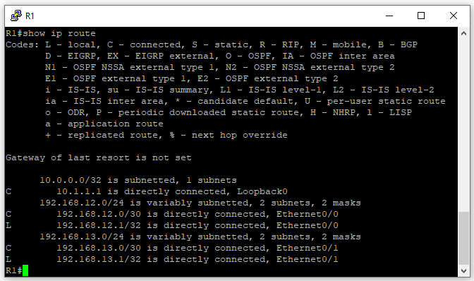
R3(config)#interface ethernet 0/1
R3(config-if)#ip address 192.168.13.2 255.255.255.252
R3(config-if)#no shutdown
R3(config-if)#exit
R3(config)#interface ethernet 0/2
R3(config-if)#ip address 192.168.23.2 255.255.255.252
R3(config-if)#no shutdown
R3(config-if)#exit
R3(config)#interface loopback 0
R3(config-if)#ip address 10.1.1.3 255.255.255.255

R1’s Routing Table
Before we configure OSPF on the routers, let’s run a show ip route to take a look at the routing table of R1. You will notice that although we have a small topology at this moment R1 isn’t aware of the network that connects R2 and R3 192.168.23.0/30.

Configure OSPF on R1

Access R1 and configure OSPF with a process ID of 1. Add each network using the appropriate wild card mask. Remember that these networks should be using Area 0 as the OSPF area ID.

R1(config)#router ospf 1
R1(config-router)#network 192.168.12.0 0.0.0.3 area 0
R1(config-router)#network 192.168.13.0 0.0.0.3 area 0
R1(config-router)#end
R1#

Configure OSPF on R2

Access R2 and configure OSPF with a process ID of 1. Add each network using the appropriate wild card mask. Remember that these networks should be using Area 0 as the OSPF area ID.

R2(config)#router ospf 1
R2(config-router)#network 192.168.12.0 0.0.0.3 area 0
R2(config-router)#network 192.168.23.0 0.0.0.3 area 0
R2(config-router)#end
R2#

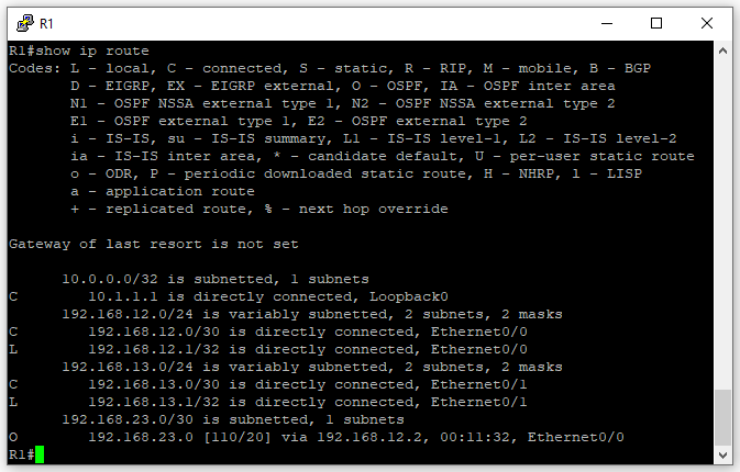
R1’s Routing table after OSPF

Now that we have configured OSPF on R1 and R2, both routers should now be OSPF neighbors. Run show ip route on R1 again to see if you now see the network between R2 and R3.

Now let’s test network connectivity, from R1 ping both IPs of the 192.168.23.0/30 network. You will notice the interface that belongs to R2 (192.168.23.1) responds back to R1. But the interface that belongs to R3 does not.

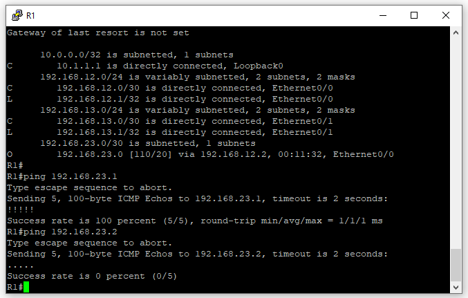
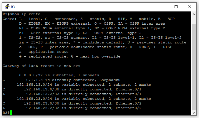
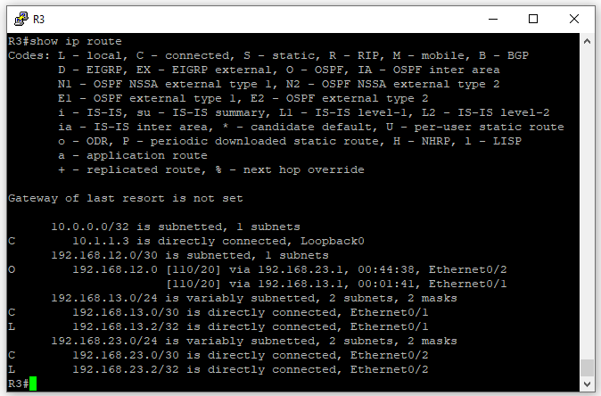
If you view R3’s routing table you will see that R3 is not aware of the network that connects R1 and R2. Therefore although the ping packets arrive to R3, since it has no way of knowing where to send the packets the ping packets are discarded.

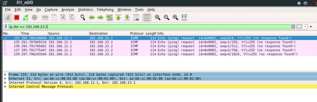
Using Wireshark on R1’s Eth 0/0 interface we can see the ICMP ping packets sent from R1’s 192.168.12.1 IP address. Because if you look at R1’s routing table it indicates the 192.168.23.0/30 network is learned via OSPF and its way out is using the Ethernet 0/0 interface.

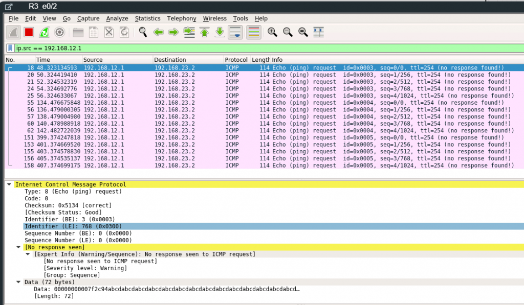
If we use Wireshark to view the traffic on R3 Eth 0/2 interface we can see the traffic arriving at R3 but no response is seen to the ICMP request because as mentioned earlier the traffic is discarded by R3 because there is no route to 192.168.12.0 on R3.

Configure OSPF on R3

Access R3 and configure OSPF with a process ID of 1. Add each network using the appropriate wild card mask. Remember that these networks should be using Area 0 as the OSPF area ID.

R3(config)#router ospf 1
R3(config-router)#network 192.168.13.0 0.0.0.3 area 0
R3(config-router)#network 192.168.23.0 0.0.0.3 area 0
R3(config-router)#end
R3#

After configuring OSPF on R3, using show ip route we can see that now R3 has the 192.168.12.0/30 network in its routing table.

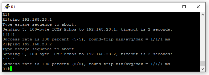
Pinging from R1 to both 192.168.23.1 & 192.168.23.2 is now successful.

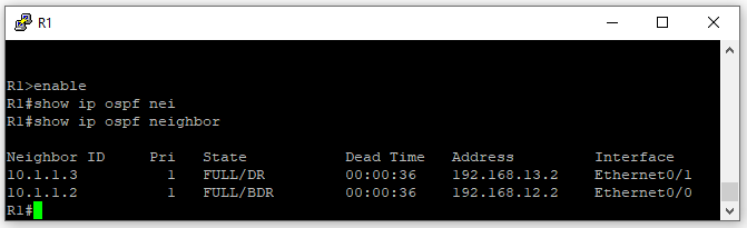
Running the show ip ospf neighbor command on R1 we can see that R1 has both R2 & R3 as OSPF neighbors. Which means R1 has established neighbor adjacencies with R2 & R3.

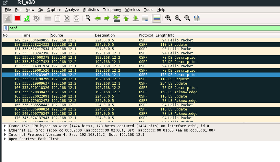
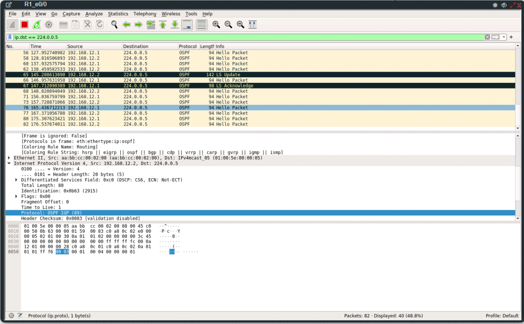
Using Wireshark on R1 interface port Eth 0/0, we can see the OSPF traffic. OSPF communicates via multicast address 224.0.0.5. For the most part, we see Hello Packets. These packets are originating from both R1’s internal interface IP address 192.168.12.1 and as well from R2 IP 192.168.12.2. We see as well a Link-State Update message and a Link-State Acknowledge message.

OSPF Message Types

OSPF uses five types of routing protocol packets, which share a common protocol header. Every OSPF packet is directly encapsulated in the IP header. The IP protocol number for OSPF is 89.

  • Type 1: Hello packet: Hello packets are used to discover, build, and maintain OSPF neighbor adjacencies. To establish adjacency, OSPF peers at both sides of the link must agree on some parameters contained in the Hello packet to become OSPF neighbors.
  • Type 2: Database Description (DBD) packet: When the OSPF neighbor adjacency is already established, a DBD packet is used to describe LSDB so that routers can compare whether databases are in sync.
  • Type 3: Link-State Request (LSR) packet: When the database synchronization process is over, the router might still have a list of LSAs that are missing in its database. The router will send an LSR packet to inform OSPF neighbors to send the most recent version of the missing LSAs.
  • Type 4: Link-State Update (LSU) packet: There are several types of LSUs, known as LSAs. LSU packets are used for the flooding of LSAs and sending LSA responses to LSR packets. It is sent only to the directly connected neighbors who have previously requested LSAs in the form of LSR packet. In case of flooding, neighbor routers are responsible for re-encapsulation of received LSA information in new LSU packets.
  • Type 5: Link-State Acknowledgment (LSAck) packet: LSAcks are used to make flooding of LSAs reliable. Each LSA received must be explicitly acknowledged. Multiple LSAs can be acknowledged in a single LSAck packet.

Observe the OSPF Adjacency Process

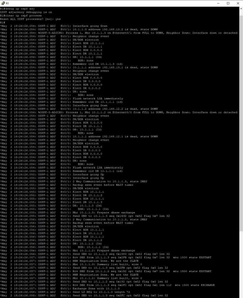
We can view the OSPF adjacency process by entering the following commands. First, enter debug ip ospf adj in the R1 terminal. Then, clear the ospf process by entering clear ip ospf process in the terminal. Observe how R1 interfaces go down. Also observe that once an OSPF Hello packet is received from its neighbor as it goes through the different states from Down to Init, then Init to 2-way. Once in 2-way the Designated Router (DR) and Backup Designated Router (BDR) election occurs. After the DR and BDR are selected the OSPF state will move to Exstart and followed by Exchange. During the Extstart and Exchange state, the routers will exchange Database Descriptor (DBD) packets. After the Exchange state, the routers will move to a Loading State where the routers will send Link-State requests followed by Link-State Acknowledge and this will continue until all Link-State update packets are acknowledged. Once complete and databases are fully synchronized the routers will move to a Full state.

We can see the exchanges on Wireshark as well. Hello Packets, Link-State Updates, Database Description (DBD), Link-State Request, and Link-State Acknowledge are all visible in the Wireshark capture.

HSRP

HSRP stands for Hot Standby Routing Protocol.
We use HSRP for gateway redundancy. Our goal is for our network to have a transparent
failover in order to achieve High Availability. We want our host to auto-magically choose a next hop
for routing IP traffic in order to recover if one of our routers were to fail. So how does HSRP work?
Well, when HSRP is configured on a network segment it provides a virtual MAC Address and an IP Address that is shared among a group of routers that are running HSRP. This virtual IP address belongs to the HSRP group, and the routers that are in this group will either be designated as the active router or be placed on Standby. So when HSRP detects that the designated active router fails, the selected standby router will assume control of the MAC and IP addresses of the HSRP group. A new standby router is also selected once the newly designated active router assumes control.

Devices that are running HSRP will send and receive multicast User Datagram Protocol (UDP) based hello packets to detect router failure.

An HSRP group consists of two or more routers running HSRP. HSRP uses a priority scheme to
determine which HSRP-configured router is to be the default active router. When configuring HSRP we assign a priority to the routers. The router with the highest priority in the group will be the default active router. The default priority value is 100, so if you configure a router to be higher than the default and the other router(s) are left at the default value, then that router will be chosen as the default active router. If the priority is the same, then the switch with the highest IP address will become the active device.

Configure the IP address assigned to the VPC device.

VPCS> set pcname VPC

VPC> ip 192.168.10.10/24 192.168.10.254

VPC> save
Saving startup configuration to startup.vpc
.  done

Configure Router 1

Properly name the device to the hostname shown in the network diagram above. Assign the appropriate IP addresses to each of the interfaces.

Router(config)#hostname R1
R1(config-if)#ip address 1.1.1.1 255.255.255.0
R1(config-if)#no shutdown
R1(config-if)#exit
R1(config)#interface ethernet 0/1
R1(config-if)#ip address 192.168.11.1 255.255.255.252
R1(config-if)#no shutdown
R1(config-if)#exit
R1(config)#interface ethernet 0/2
R1(config-if)#ip address 192.168.12.1 255.255.255.252
R1(config-if)#no shutdown
R1(config-if)#exit

Configure both of the multilayer switches MLSW1 & MLSW2

Properly name the device to the hostname shown in the network diagram above. Assign the appropriate IP address to the interface connected to R1. Name VLAN 10 to “v10-Host”. Assign the correct IP address to VLAN 10. Assign the interface connected to the Layer 2 switch to VLAN 10.

Switch(config)#hostname MLSW1
MLSW1(config)#interface ethernet 0/3
MLSW1(config-if)#no switchport
MLSW1(config-if)#ip address 192.168.11.2 255.255.255.252
MLSW1(config-if)#no shutdown
MLSW1(config-if)#exit
MLSW1(config)#vlan 10
MLSW1(config-vlan)#name v10-Host
MLSW1(config-vlan)#exit
MLSW1(config)#interface vlan 10
MLSW1(config-if)#ip address 192.168.10.1 255.255.255.0
MLSW1(config)#interface ethernet 0/2
MLSW1(config-if)#switchport access vlan 10


Switch(config)#hostname MLSW2
MLSW2(config)#interface ethernet 0/3
MLSW2(config-if)#no switchport
MLSW2(config-if)#ip address 192.168.12.2 255.255.255.252
MLSW2(config-if)#no shutdown
MLSW2(config-if)#exit
MLSW2(config)#vlan 10
MLSW2(config-vlan)#name v10-Host
MLSW2(config-vlan)#exit
MLSW2(config)#interface vlan 10
MLSW2(config-if)#no shutdown
MLSW2(config-if)#exit
MLSW2(config)#interface ethernet 0/2
MLSW2(config-if)#switchport access vlan 10

Configure OSPF on R1, MLSW1 & MLSW2

To set up interconnectivity between all the networks, let’s use OSPF. Using OSPF process ID 1, assign the appropriate router-id to each device and add all the local networks of R1, MLSW1 & MLSW2. The OSPF area ID should be set to 0.

R1(config)#router ospf 1
R1(config-router)#router-id 172.16.0.1
R1(config-router)#network 1.1.1.0 0.0.0.255 area 0
R1(config-router)#network 192.168.11.0 0.0.0.3 area 0
R1(config-router)#network 192.168.12.0 0.0.0.3 area 0

MLSW1(config)#router ospf 1
MLSW1(config-router)#router-id 172.16.0.2
MLSW1(config-router)#network 192.168.11.0 0.0.0.3 area 0
MLSW1(config-router)#network 192.168.10.0 0.0.0.255 area 0

MLSW2(config)#router ospf 1
MLSW2(config-router)#router-id 172.16.0.3
MLSW2(config-router)#network 192.168.12.0 0.0.0.3 area 0
MLSW2(config-router)#network 192.168.10.0 0.0.0.255 area 0

Enable HSRP on MLSW1 & MLSW2

Assign the VLAN 10 interface on both MLSW1 & MLSW2 to HSRP group 1 using the Virtual IP address 192.168.10.254. Leave the default HSRP priority to 100 on both switches.

MLSW1(config)#interface vlan 10
MLSW1(config-if)#standby 1 ip 192.168.10.254

MLSW2(config)#interface vlan 10
MLSW2(config-if)#standby 1 ip 192.168.10.254

Using show commands determine which switch is set to Active

Either using the show command “show standby” or “show standby brief” on either of the switches determine which is set to active and which is set to standby. “show standby” is verbose and shows more information.

The show command “show standby brief” provides similar information in a shorter form. In the “standby brief” table the State column will indicate whether it’s active or standby, you can see in the image below that MLSW1 has been set to Active.

Set the priority higher than the default on either switch

Choose either MLSW1 or MLSW2 and set the priority to 150. In this example, I set MLSW2 to priority 150.

MLSW2(config-if)#standby 1 priority 150

Run the show command “show standby brief” on the switch that you increased the priority of.

You may be wondering why if changing the priority to a higher priority, why hasn’t that switch now become the Active switch? We will need to use preempt in order for the switch to become the new Active switch. By default, preemption will take effect immediately but it might be a good idea to use a delay. If a router reboots it might need some time to “converge”. Maybe OSPF or EIGRP will need to form neighbor adjacencies or the spanning tree isn’t ready yet to unblock the ports. Therefore I am going to set the delay to a minimum of 60 seconds.

MLSW2(config)#interface vlan 10
MLSW2(config-if)#standby 1 preempt delay minimum 60

After a minute has passed recheck to see if now the switch has become the Active switch. You can see in the image below the Syslog message that indicates an HSRP state change to Active, and running the show command “show standby brief” confirms it.

From the host pc “VPC1”, let’s ping the default gateway. Which should be the Virtual gateway IP address. After pinging the virtual gateway proceed to ping both MLSW1 & MLSW2 VLAN 10 IP addresses. Then run the arp command. As you can see the MAC addresses of the VLAN 10 interfaces are different from the virtual gateway MAC address.

By default, HSRP is pretty slow. MLSW1 is my standby router and it will wait for 10 seconds (hold time) before it will become active once MLSW2 fails. That means we’ll have 10 seconds of downtime… We can speed the standby timer up. Let’s change the Hello timer to 1 second and the hold timer for 4 seconds.

MLSW1(config)#interface vlan 10
MLSW1(config-if)#standby 1 timers 1 4

MLSW2(config)#interface vlan 10
MLSW2(config-if)#standby 1 timers 1 4

Using WireShark on MLSW2 Ethernet 0/2 interface you can see the HSRP Hello traffic. We see that this communication is done by using the multicast address 224.0.0.2.

There are two versions of HSRP and depending on the router or switch model you might have the option to use HSRP version 2. You can change the version by using the standby version command. Let’s change the HSRP version to version 2. On both MLSW1 and MLSW2 change the version to version 2.

MLSW1(config)#interface vlan 10
MLSW1(config-if)#standby version 2

MLSW2(config)#interface vlan 10
MLSW2(config-if)#standby version2

In the table are some of the differences between HSRPv1 and HSRPv2

HSRPv1HSRPv2
Group Numbers0 – 2550 – 4095
Virtual MAC address0000.0c07.acXX (XX = group number)0000.0c9f.fxxx (XXX = group number)
Multicast Address224.0.0.2224.0.0.102

Now that we have changed the HSRP version, using Wireshark we can see that the Hello HSRP packet is using a different multicast address 224.0.0.102.

This concludes the HSRP lab. I hope you enjoyed it and learned from it.

Cisco ACL lab

In this lab, we will run through the process of setting up a small network. We will use this network to show the different types of ACLs. We will start by using a standard named ACL in order to allow traffic to use NAT (PAT) to permit our workstation LAN network to access the internet. We will then create an extended network to permit web traffic but block others.


Change hostname Rtr-1
Access the router and change the hostname to ‘Rtr-1’. Configure the router to use Google’s DNS IP ‘8.8.8.8’.

Router>enable
Router#configure terminal
Enter configuration commands, one per line.  End with CNTL/Z.
Router(config)#hostname Rtr-1
Rtr-1(config)#ip domain-lookup
Rtr-1(config)#ip name-server 8.8.8.8

Configure Rtr-1 Interfaces
Configure each interface of Rtr-1 as they appear in the table above.

Rtr-1(config)#interface Gi0/0
Rtr-1(config-if)#ip address dhcp
Rtr-1(config-if)#no shutdown
Rtr-1(config-if)#exit
Rtr-1(config)#interface Gi0/1
Rtr-1(config-if)#ip address 192.168.5.1 255.255.255.0
Rtr-1(config-if)#no shutdown
Rtr-1(config-if)#exit
Rtr-1(config)#interface Gi0/2
Rtr-1(config-if)#ip address 10.200.1.1 255.255.255.240
Rtr-1(config-if)#no shutdown
Rtr-1(config-if)#exit
Rtr-1(config)#

Create a DHCP server on Router 1 name it Workstation-LAN
Setup a DHCP Pool named Workstation-LAN. Set the network as 192.168.5.0/24. Configure the DNS server to use Google’s DNS server IP address ‘8.8.8.8’. Set the gateway as the IP assigned to interface Gi 0/1. Reserve the first 25 IPs and the last 55 IPs.

Rtr-1(config)#ip dhcp pool Workstation-LAN
Rtr-1(dhcp-config)#network 192.168.5.0 255.255.255.0
Rtr-1(dhcp-config)#default-router 192.168.5.1
Rtr-1(dhcp-config)#dns-server 8.8.8.8
Rtr-1(dhcp-config)#exit
Rtr-1(config)#ip dhcp excluded-address 192.168.5.1 192.168.5.25
Rtr-1(config)#ip dhcp excluded-address 192.168.5.201 192.168.5.255


Set up PC-1 to a Dynamic IP address
I am using a Docker container in this lab, but you can use a Linux VM, Windows VM, or even a Virtual PC. If you are using the Docker container in EVE-NG make sure to Enable DHCP on Eth 0 is checked in the configuration window.

Set up Web-Svr as a Static IP
Configure the Web Server to use a static IP as it appears in the table above. Using a terminal configure the IP address. In this lab, I used a Docker container you can use a Linux VM, Windows VM, or a Virtual PC.

root@Web-Svr:~# ip addr add 10.200.1.4/28 dev eth0
root@Web-Svr:~# ip route add default via 10.200.1.1

Configure NAT Overload (PAT) on Rtr-1
Define the inside and outside interfaces on Rtr-1. Create a standard named ACL, using the name ‘NAT-ACL’. Permit the Workstation-LAN on the ACL. Set the ACL ‘NAT-ACL’ as the inside source and set the outside interface to overload.

Rtr-1(config)#interface Gi0/0
Rtr-1(config-if)#ip nat outside
Rtr-1(config-if)#exit
Rtr-1(config)#interface Gi0/1
Rtr-1(config-if)#ip nat inside
Rtr-1(config-if)#exit
Rtr-1(config)#ip access-list standard NAT-ACL
Rtr-1(config-std-nacl)#permit 192.168.5.0 0.0.0.255
Rtr-1(config-std-nacl)#exit
Rtr-1(config)#ip nat inside source list NAT-ACL interface Gi0/0 overload

Verify PC-1 can access internet websites
Open an RDP session to PC-1 and open a web browser and connect to any website to verify connectivity.

Start a simple web server
If you are using Docker Container in Eve-NG Pro ‘Gui-Server’ as I did you will not need to follow these instructions. If you are using a Linux VM add the following commands in the Linux terminal.

sudo apt update
sudo apt install apache2

After entering those commands you should be able to open the PC-1 web browser and access the apache webserver by typing the Web-Svr IP in the search bar of the browser like so ‘http://10.200.1.4’.

Start a Python SimpleHTTP Server on port 8080
Return back to the Web-Svr terminal and enter the following command in order to start an additional webserver on the Web-Svr.

root@Web-Svr:~# python -m SimpleHTTPServer 8080
Serving HTTP on 0.0.0.0 port 8080 ...

After entering those commands you should be able to open the PC-1 web browser and access the SimpleHTTPServer app using port 8080 and the IP address of the Web-Svr.

Create an extended ACL to block PC-1 access to port 80 but continue to permit 8080
Access Rtr-1 and configure an extended ACL using the access-list number 104. Assign the ACL to the appropriate interface. Remember the ACL created should be configured closer to the source.

Rtr-1(config)#ip access-list extended 104
Rtr-1(config-ext-nacl)#permit tcp host 192.168.5.26 host 10.200.1.4 eq 8080
Rtr-1(config-ext-nacl)#deny tcp host 192.168.5.26 host 10.200.1.4 eq 80
Rtr-1(config-ext-nacl)#exit
Rtr-1(config)#interface Gi0/1
Rtr-1(config-if)#ip access-group 104 in

Verify that PC-1 no longer has access to Port 80 of the Web-Svr

Verify the PC-1 still has access to port 8080 of the Web-Svr

Uh oh PC-1 No longer has access to the internet.

Fix the ACL so that PC-1 regains Internet Access
Change the ACL to permit all other traffic before the implicit deny.

Rtr-1(config)#ip access-list extended 104
Rtr-1(config-ext-nacl)#permit ip any any
Rtr-1(config-ext-nacl)#end

Verify that PC-1 can now access the internet after the ACL changes

You have completed the lab.

Managing Cisco Devices

Managing your Cisco Switches and Routers are essential to maintaining a healthy network. They’re numerous protocols, features, and technologies used throughout data centers across the globe to assist network administrators to support their network. While it would be hard to show everything in a lab all the technologies we can concentrate on core network protocols that are essential to managing your devices. In this lab, we are going to use some well-known protocols and features: NTP, SNMPv3, Syslog, ACLs, and TFTP.

Using the previously configured lab “GRE Tunnel Lab” we are going to expand and configure the Washington DC site to use these technologies. I will also use an Ubuntu server to assist in using these tools in order to manage the devices.

Configure a banner
Using banner motd, create a banner to deter unauthorized users from logging on to Router R1.

R1>enable
Password:
R1#configure terminal
Enter configuration commands, one per line.  End with CNTL/Z.
R1(config)#banner motd #
Enter TEXT message.  End with the character '#'.
This device is for authorized personnel only.
If you have not been provided with permission to
access this devices - disconnect at once.

#
R1(config)#

Create an ACL to protect access to R1
Using a standard ACL, permit only the Linux-Mgmt Server (192.168.10.129) to access via SSH Router R1. Make sure to log all denied traffic and successful entries.

R1(config)#ip access-list standard 5
R1(config-std-nacl)#remark Permitted-Devices-VTY
R1(config-std-nacl)#permit 192.168.10.129 log
R1(config-std-nacl)#deny any log
R1(config-std-nacl)#exit
R1(config)#line vty 0 4
R1(config-line)#access-class 5 in
R1(config-line)#transport input ssh
R1(config-line)#exit
R1(config)#

Configure NTP on Router R1
Set Router R1 to use Google’s Public NTP server. Verify that the Router can ping the server “time1.google.com”. Set the time zone to your appropriate time zone.

R1(config)#do ping time1.google.com
Translating "time1.google.com"...domain server (8.8.8.8) [OK]

Type escape sequence to abort.
Sending 5, 100-byte ICMP Echos to 216.239.35.0, timeout is 2 seconds:
!!!!!
Success rate is 100 percent (5/5), round-trip min/avg/max = 17/18/19 ms
R1(config)#ntp server time1.google.com
R1(config)#clock timezone EDT -4
R1(config)#
*Jun  4 01:02:54.589: %SYS-6-CLOCKUPDATE: System clock has been updated from 20:02:54 EST Thu Jun 3 2021 to 21:02:54 EDT Thu Jun 3 2021, configured from console by console.

Verify NTP
Verify that an NTP server is configured and that the time source is from the NTP server. Note* Clock synchronization make take a few minutes to appear as synchronized.

Configure SNMPv3 on R1
Create a new SNMPv3 group named ‘network-admin’. Set the group to use the ‘AuthPriv’ security level. Create a SNMPv3 user ‘snmpadmin’ and assign to the newly created ‘network-admin’ group. Set the authentication protocol to SHA and the privacy encryption algorithm to AES 128. Verify the user was properly created by using ‘show snmp user’.

R1(config)#snmp-server group network-admin v3 ?
  auth    group using the authNoPriv Security Level
  noauth  group using the noAuthNoPriv Security Level
  priv    group using SNMPv3 authPriv security level

R1(config)#snmp-server group network-admin v3 priv
R1(config)#snmp-server user snmpadmin network-admin v3 auth sha CIsco#1234 priv aes 128 ciSCO1234#
R1(config)#
R1(config)#do show snmp user

User name: snmpadmin
Engine ID: 800000090300AABBCC000100
storage-type: nonvolatile        active
Authentication Protocol: SHA
Privacy Protocol: AES128
Group-name: network-admin

Configure password and add new user on Sw1
Configure an enable password. Create a new user with a secret password. Using banner motd, create a banner to deter unauthorized users from logging on to Switch Sw1.

Sw1>enable
Sw1#configure terminal
Enter configuration commands, one per line.  End with CNTL/Z.
Sw1(config)#enable secret cisco
Sw1(config)#username admin secret $trongP@$$word1234
Sw1(config)#banner motd #
Enter TEXT message.  End with the character '#'.
This device is for authorized personnel only.
If you have not been provided with permission to
access this device - disconnect at once.
#

Assign an IP to Sw1
Assign an IP from the Out-of-band Management VLAN. Add a default route to the VLANs gateway address. Verify connectivity by pinging the gateway and user device from Users VLAN.

Sw1(config)#interface vlan 30
*Jun  4 02:27:36.229: %LINEPROTO-5-UPDOWN: Line protocol on Interface Vlan30, changed state to down
Sw1(config-if)#ip address 192.168.10.157 255.255.255.224
Sw1(config-if)#no shutdown
Sw1(config-if)#exit
Sw1(config)#ip route 0.0.0.0 0.0.0.0 192.168.10.158
Sw1(config)#do ping 192.168.10.158
Type escape sequence to abort.
Sending 5, 100-byte ICMP Echos to 192.168.10.158, timeout is 2 seconds:
.!!!!
Success rate is 80 percent (4/5), round-trip min/avg/max = 1/1/1 ms
Sw1(config)#do ping 192.168.10.1
Type escape sequence to abort.
Sending 5, 100-byte ICMP Echos to 192.168.10.1, timeout is 2 seconds:
!!!!!
Success rate is 100 percent (5/5), round-trip min/avg/max = 1/1/1 ms

Configure a domain name
Assign a domain “mylab.local” to the Switch Sw1.

Sw1(config)#ip domain-name mylab.local

Configure SSH
Generate a RSA key. Set the modulus bits to 2048. Make sure you use SSH version 2.

Sw1(config)#crypto key generate rsa
The name for the keys will be: Sw1.mylab.local
Choose the size of the key modulus in the range of 360 to 4096 for your
  General Purpose Keys. Choosing a key modulus greater than 512 may take
  a few minutes.

How many bits in the modulus [512]: 2048
% Generating 2048 bit RSA keys, keys will be non-exportable...
[OK] (elapsed time was 10 seconds)

Sw1(config)#
*Jun  4 02:55:56.917: %SSH-5-ENABLED: SSH 1.99 has been enabled
Sw1(config)#ip ssh version 2

Configure ACL to protect access to Sw1
Using a standard ACL, permit only the Linux-Mgmt Server (192.168.10.129) to access via SSH Switch Sw1. Make sure to log all denied traffic and successful entries.

Sw1(config)#ip access-list standard 5
Sw1(config-std-nacl)#remark Permitted-Devices-VTY
Sw1(config-std-nacl)#permit 192.168.10.129 log
Sw1(config-std-nacl)#deny any log
Sw1(config-std-nacl)#exit
Sw1(config)#line vty 0 4
Sw1(config-line)#access-class 5 in
Sw1(config-line)#transport input ssh
Sw1(config-line)#login local
Sw1(config-line)#exit
Sw1(config)#

Configure NTP on Switch Sw1
Set Switch Sw1 to use Router R1 Management IP. Set the timezone to your appropriate timezone.

Sw1(config)#ntp server 192.168.10.158
Sw1(config)#clock timezone EDT -4
Sw1(config)#
*Jun  4 03:20:40.848: %SYS-6-CLOCKUPDATE: System clock has been updated from 22:20:40 EST Thu Jun 3 2021 to 23:20:40 EDT Thu Jun 3 2021, configured from console by console.

Verify NTP
Verify that an NTP server is configured and that the time source is from the NTP server. Note* Clock synchronization make take a few minutes to appear as synchronized.

Verify connectivity to Sw-1
Verify the connectivity from the Linux-Mgmt workstation to the Switch Sw-1 using SSH.

For the following portion of the lab, we will need to provide internet access to the Linux-Mgmt workstation. In the previous lab, we did not allow VLAN 30 access to the internet. Now we will need to permit internet access in order to install the needed applications and updates. In order to do so, we will need to make a couple of changes to the Router to permit the traffic.

R1(config)#ip access-list standard 10
R1(config-std-nacl)#30 permit 192.168.10.128 0.0.0.31
R1(config-std-nacl)#exit
R1(config)#
R1(config)#interface ethernet 0/0.30
R1(config-subif)#ip nat inside
R1(config-subif)#exit
R1(config)#

Install TFTP on Ubuntu
Using the following command “sudo apt install tftpd-hpa”, install tftpd-hpa service.

Verify TFTP service is active
Using the following command “sudo systemctl status tftpd-hpa”, to verify if the service is active.


Edit tftpd-hpa configuration file
We need to edit a couple of things in order to get tftp running properly and allow our cisco devices to save their configs. Use the following command “sudo nano /etc/default/tftpd-hpa”.

We will need to add –create in TFTP_OPTIONS because that gives us the ability to add new files. Without the –create option, you won’t be able to create or upload new files to the TFTP server. In addition, we will change the directory of the tftp server to “/tftp”.
TFTP_USERNAME=”tftp”
TFTP_DIRECTORY=”/tftp”
TFTP_ADDRESS=”:69″
TFTP_OPTIONS=”–secure –create”

Make the new TFTP directory
Now that we have changed the tftp directory to “/tftp” we will need to create that directory as it doesn’t exist. Use the following command in order to create the directory “sudo mkdir /tftp”.

Permit TFTP service to write to the directory
In order to allow tftp service to write the directory, we will change the ownership of the directory and this will allow the tftp service to permit it to write to the directory. Use the following command “sudo chown tftp:tftp /tftp”.

Restart the TFTP server
In order for the changes to take we will need to restart the service. Enter the following command “sudo systemctl restart tftpd-hpa” this will restart the service.

From Router R1 copy configs
Go back to the router and using the “copy run tftp:” command copy the running-config to the server.

Install SNMP on Ubuntu
Using the following command “sudo apt install snmp”, to install SNMP on the linux workstation.

Test SNMP configurations
Using the following SNMP walk command “snmpwalk -v 3 -u snmpadmin -l authPriv -a sha -A CIsco#1234 -x aes -X ciSCO1234# 192.168.10.158” in order to verify that SNMP was properly configured on the router.

Install rsyslog on Ubuntu
Using the following command to install rsyslog “sudo apt install rsyslog”.

Verify the rsyslog service is running
To verify that rsyslog service is running on the server, use the following command “sudo systemctl status rsyslog”.

Configure rsyslog to run in Server mode
Edit the rsyslog config file using nano, do this by entering the following command “sudo nano /etc/rsyslog.conf”. Once the file is loaded look for the following lines and un-comment them by removing the ‘#’ symbol in front of the line.

module(load="imudp")
input(type="imudp" port="514")

module(load="imtcp")
input(type="imtcp" port="514")

Create remote-incoming-logs template
Create a new template for receiving remote messages and add it just before GLOBAL DIRECTIVES. Enter the following lines.

$ModLoad imudp $UDPServerRun 514
local7.* /var/log/cisco

$AllowedSender UDP, 127.0.0.1, 192.168.10.158

Create the file ‘cisco’
Create the file so that it may receive the data by using the following command “sudo touch cisco” while in the ‘/var/log/’ directory. If you are not in said directory make sure you change to the appropriate directory by using the cd command “cd /var/log/”.

Configure on R1 Syslog
Send the Syslog data to the Linux-Mgmt workstation 192.168.10.129. Add the source interface. Make sure to log user info, and set the logging severity level to receive informational level 6. Add the hostname as the origin-id so that the Syslog data sent will display the hostname of the router.

R1(config)#logging host 192.168.10.129
R1(config)#
Jun 11 00:42:22.555: %SYS-6-LOGGINGHOST_STARTSTOP: Logging to host 192.168.10.129 port 514 started - CLI initiated
R1(config)#logging source-interface ethernet 0/0.30
R1(config)#logging userinfo
R1(config)#logging trap 6
R1(config)#logging origin-id hostname
R1(config)#logging on

Verify the Syslog data on Server
Using cat followed by the filename display the contents of the Syslog data received by the server.

Here’s a video of me doing this particular lab. Catch more like these on my Youtube Channel.

GRE Tunnel Lab

I completed an example of this lab and posted the video on YouTube. You can view the video in the link below. I plan on posting more labs like the ones found on my blog on that channel. Please subscribe and leave a comment that you found the link through my blog.

Generic Routing Encapsulation (GRE) is a tunneling protocol that provides the ability of routers to transport packets of one protocol over another protocol. This is done by way of encapsulation. Encapsulation is the process of enclosing the data of a packet inside another packet. It also provides the ability to create virtual interfaces that can connect two different sites that are not in near proximity, and appear to be adjacent from each other. With this technology, we can use unicast, broadcast, and multicast communication over this virtual interface. Because multicast is allowed to be encapsulated through a GRE Tunnel we can use Interior Gateway Routing Protocols to exchange routes between the sites and yes even through the internet.

Configure Router R1
Set the hostname. Configure the interfaces and sub-interfaces ip addresses to match the table above. The Sub-Interfaces shall use encapsulation dot1q and the specific sub-interfaces should match the VLAN-ID. Set interface ethernet 0/1 to receieve its IP Address automatically using DHCP.

Router>enable
Router#configure terminal
Enter configuration commands, one per line.  End with CNTL/Z.
Router(config)#hostname R1
R1(config)#interface ethernet 0/0
R1(config-if)#no ip address
R1(config-if)#no shutdown
R1(config-if)#interface ethernet 0/0.24
R1(config-subif)#encapsulation dot1q 24
R1(config-subif)#ip address 192.168.10.126 255.255.255.128
R1(config-subif)#exit
R1(config)#interface ethernet 0/0.30
R1(config-subif)#encapsulation dot1q 30
R1(config-subif)#ip address 192.168.10.158 255.255.255.224
R1(config-subif)#exit
R1(config)#interface ethernet 0/0.45
R1(config-subif)#encapsulation dot1q 45
R1(config-subif)#ip address 192.168.10.190 255.255.255.224
R1(config-subif)#exit
R1(config)#interface ethernet 0/1
R1(config-if)#ip address dhcp
R1(config-if)#no shutdown
*May 22 02:19:43.849: %DHCP-6-ADDRESS_ASSIGN: Interface Ethernet0/1 assigned DHCP address 172.29.129.129, mask 255.255.255.0, hostname R1
R1(config-if)#exit

**Note: The IP address on the outbound interface (Ethernet 0/1) may also be configured manually if DHCP is not an option.

Configure Switch Sw1
Set the hostname. Create the VLANs (VLAN 24, 30, and 45) and assign the descriptive name as it appears in the table above. Configure the trunk using encapsulation dot1q and allow the VLANs created. Configure the access ports and assign the appropriate VLAN to the interface.

Switch>enable
Switch#configure terminal
Enter configuration commands, one per line.  End with CNTL/Z.
Switch(config)#hostname Sw1
Sw1(config)#vlan 24
Sw1(config-vlan)#name Users
Sw1(config-vlan)#exit
Sw1(config)#vlan 30
Sw1(config-vlan)#name Management
Sw1(config-vlan)#exit
Sw1(config)#vlan 45
Sw1(config-vlan)#name Servers
Sw1(config-vlan)#exit
Sw1(config)#interface ethernet 1/3
Sw1(config-if)#switchport trunk encapsulation dot1q
Sw1(config-if)#switchport mode trunk
Sw1(config-if)#switchport trunk allowed vlan 24,30,45
Sw1(config-if)#exit
Sw1(config)#interface ethernet 0/0
Sw1(config-if)#switchport mode access
Sw1(config-if)#switchport access vlan 24
Sw1(config-if)#exit
Sw1(config)#interface ethernet 0/1
Sw1(config-if)#switchport mode access
Sw1(config-if)#switchport access vlan 24
Sw1(config-if)#exit
Sw1(config)#interface ethernet 0/2
Sw1(config-if)#switchport mode access
Sw1(config-if)#switchport access vlan 30
Sw1(config-if)#exit
Sw1(config)#interface ethernet 0/3
Sw1(config-if)#switchport mode access
Sw1(config-if)#switchport access vlan 45
Sw1(config-if)#exit

Configure Router R2
Set the hostname. Configure the interfaces and sub-interfaces IP addresses to match the table above. The Sub-Interfaces shall use encapsulation dot1q and the specific sub-interfaces should match the VLAN-ID. Set interface ethernet 0/1 to receive its IP Address automatically using DHCP.

Router>enable
Router#configure terminal
Enter configuration commands, one per line.  End with CNTL/Z.
Router(config)#hostname R2
R2(config)#interface ethernet 0/0
R2(config-if)#no ip address
R2(config-if)#no shutdown
R2(config-if)#interface ethernet 0/0.15
R2(config-subif)#encapsulation dot1q 15
R2(config-subif)#ip address 192.168.20.62 255.255.255.192
R2(config-subif)#exit
R2(config)#interface ethernet 0/0.21
R2(config-subif)#ip address 192.168.20.94 255.255.255.224
R2(config)#interface ethernet 0/1
R2(config-if)#ip address dhcp
R2(config-if)#no shutdown
*May 22 02:24:09.219: %DHCP-6-ADDRESS_ASSIGN: Interface Ethernet0/1 assigned DHCP address 172.29.129.61, mask 255.255.255.0, hostname R2
R2(config-if)#exit

**Note: The IP address on the outbound interface (Ethernet 0/1) may also be configured manually if DHCP is not an option.

Configure GRE Tunnel on Router R1
Assign the IP address to the tunnel interface as listed in the diagram above. Set the source interface using the outbound interface. Provide the destination IP, the IP should be the outbound interface IP of router R2.

R1(config)#interface tunnel 12
R1(config-if)#ip address 10.0.12.1 255.255.255.252
R1(config-if)#tunnel source Ethernet0/1
R1(config-if)#tunnel destination 172.29.129.61
R1(config-if)#exit

Configure GRE Tunnel on Router R2
Assign the IP address to the tunnel interface as listed in the diagram above. Set the source interface using the outbound interface. Provide the destination IP, the IP should be the outbound interface IP of router R1.

R2(config)#interface tunnel 12
R2(config-if)#ip address 10.0.12.1 255.255.255.252
R2(config-if)#tunnel source Ethernet0/1
R2(config-if)#tunnel destination 172.29.129.129
R2(config-if)#exit

Verify the tunnel is up and operational
Ping R2 tunnel’s interface from Router R1. Using ‘show ip interface brief’ verify that the tunnel is up.

Configure EIGRP on Router R1
Using AS (Autonomous System) 1, configure EIGRP. Set the routing protocol to not auto-summarize. Advertise the sub-interfaces networks and the GRE Tunnel subnet using the wildcard mask set the limits of the advertised networks.

R1#configure terminal
R1(config)#router eigrp 1
R1(config-router)#no auto-summary
R1(config-router)#network 192.168.10.0 0.0.0.127
R1(config-router)#network 192.168.10.128 0.0.0.31
R1(config-router)#network 192.168.10.160 0.0.0.31
R1(config-router)#network 10.0.12.0 0.0.0.3

Configure EIGRP on Router R2
Using AS (Autonomous System) 1, configure EIGRP. Set the routing protocol to not auto-summarize. Advertise the sub-interfaces networks and the GRE Tunnel subnet using the wildcard mask set the limits of the advertised networks.

R2#configure terminal
R2(config)#router eigrp 1
R2(config-router)#no auto-summary
R2(config-router)#network 192.168.20.0 0.0.0.63
R2(config-router)#network 192.168.20.64 0.0.0.31
R2(config-router)#network 10.0.12.0 0.0.0.3

Verify that Router R2 has learned Router R1 internal networks
Using ‘show ip route eigrp’ verify that router R2 has learned the networks advertised from router R1.

EIGRP – Lab for IPv4

Configure Router R1
Set the hostname. Create a banner. Configure the interfaces and sub-interfaces that match the table above. Create a DHCP pool for Hosts VLAN 12.

Router>enable
Router#configure terminal
Enter configuration commands, one per line.  End with CNTL/Z.
Router(config)#hostname R1
R1(config)#no ip domain-lookup
R1(config)#banner # R1 -> Stay out of the this Router if you are not authorized #
R1(config)#interface g0/0
R1(config-if)#ip address 10.0.12.1 255.255.255.0
R1(config-if)#no shutdown
R1(config-if)#exit
R1(config)#interface g0/1
R1(config-if)#no ip address
R1(config-if)#no shutdown
R1(config)#interface g0/1.11
R1(config-subif)#encapsulation dot1q 11
R1(config-subif)#ip address 172.16.1.1 255.255.255.0
R1(config-subif)#no shutdown
R1(config-subif)#exit
R1(config)#interface g0/1.12
R1(config-subif)#encapsulation dot1q 12
R1(config-subif)#ip address 192.168.1.1 255.255.255.0
R1(config-subif)#no shutdown
R1(config-subif)#exit
R1(config)#ip dhcp pool Hosts-Vlan-12
R1(dhcp-config)#network 192.168.1.0 255.255.255.0
R1(dhcp-config)#default-router 192.168.1.1
R1(dhcp-config)#exit

Configure Router R2
Set the hostname. Create a banner. Configure the interfaces.

Router>enable
Router#configure terminal
Enter configuration commands, one per line.  End with CNTL/Z.
Router(config)#hostname R2
R2(config)#no ip domain-lookup
R2(config)#banner # R2 -> Stay out of this Router if you are not authorized #
R2(config)#interface g0/0
R2(config-if)#ip address 10.0.12.2 255.255.255.0
R2(config-if)#no shutdown
R2(config-if)#exit
R2(config)#interface g0/1
R2(config-if)#ip address 10.0.23.2 255.255.255.0
R2(config-if)#no shutdown
R2(config-if)#exit

Configure Router R3
Set the hostname. Create a banner. Configure the interfaces and the loopback 0 address.

Router>enable
Router#configure terminal
Enter configuration commands, one per line.  End with CNTL/Z.
Router(config)#hostname R3
R3(config)#no ip domain-lookup
R3(config)#banner # R3 -> Stay out of this Router if you are not authorized #
R3(config)#interface g0/0
R3(config-if)#ip address 10.0.23.3 255.255.255.0
R3(config-if)#no shutdown
R3(config-if)#interface loopback 0
R3(config-if)#ip address 192.168.3.1 255.255.255.0
R3(config-if)#no shutdown
R3(config-if)#interface g0/1
R3(config-if)#ip address 172.16.13.1 255.255.255.0
R3(config-if)#no shutdown

Configure Switch DSw1
Set the hostname. Create a banner. Create VLANs 11 & 12. Configure its uplink port as a trunk that allows only VLANs 11 & 12. Configure port E0/1 to access VLAN 11 and configure port E1/3 to access VLAN 12.

Switch>enable
Switch#configure terminal
Enter configuration commands, one per line.  End with CNTL/Z.
Switch(config)#hostname DSw1
DSw1(config)#no ip domain-lookup
DSw1(config)#banner # DSw1 -> Stay out of this switch if you are not authorized #
DSw1(config)#vlan 11
DSw1(config-vlan)#name Management-VLAN
DSw1(config-vlan)#exit
DSw1(config)#vlan 12
DSw1(config-vlan)#name Hosts-VLAN
DSw1(config-vlan)#exit
DSw1(config)#interface ethernet 1/1
DSw1(config-if)#switchport trunk encapsulation dot1q
DSw1(config-if)#switchport mode trunk
DSw1(config-if)#switchport trunk allowed vlan 11-12
DSw1(config-if)#exit
DSw1(config)#interface ethernet 1/3
DSw1(config-if)#switchport mode access
DSw1(config-if)#switchport access vlan 12
DSw1(config-if)#exit
DSw1(config)#interface ethernet 0/1
DSw1(config-if)#switchport mode access
DSw1(config-if)#switchport access vlan 11
DSw1(config-if)#no shutdown

Configure Switch DSw2
Set the hostname. Create a banner. Configure the interfaces E1/1 & E0/1 as Layer three ports with the correct IP addresses.

Switch>enable
Switch#configure terminal
Enter configuration commands, one per line.  End with CNTL/Z.
Switch(config)#hostname DSw2
DSw2(config)#no ip domain-lookup
DSw2(config)#banner # DSw2 -> Stay out of this switch if you are not authorized #
DSw2(config)#interface ethernet 0/1
DSw2(config-if)#no switchport
DSw2(config-if)#ip address 172.16.1.2 255.255.255.0
DSw2(config-if)#no shutdown
DSw2(config-if)#exit
DSw2(config)#interface ethernet 1/1
DSw2(config-if)#no switchport
DSw2(config-if)#ip address 172.16.13.2 255.255.255.0
DSw2(config-if)#no shutdown
DSw2(config-if)#exit
DSw2(config)#

Configure PC PC1
Set the hostname. Using DHCP allow the PC to retrieve an IP address. Ping its gateway to verify connectivity. Save configurations.

VPCS> set pcname PC1
PC1> ip dhcp
DDORA IP 192.168.1.2/24 GW 192.168.1.1

PC1> ping 192.168.1.1

84 bytes from 192.168.1.1 icmp_seq=1 ttl=255 time=6.099 ms
84 bytes from 192.168.1.1 icmp_seq=2 ttl=255 time=4.406 ms
84 bytes from 192.168.1.1 icmp_seq=3 ttl=255 time=2.373 ms
84 bytes from 192.168.1.1 icmp_seq=4 ttl=255 time=3.879 ms
84 bytes from 192.168.1.1 icmp_seq=5 ttl=255 time=2.407 ms

PC1> save
Saving startup configuration to startup.vpc
.  done

Implement EIGRP for IPv4
Configure classic EIGRP for IPv4 on all devices. Use Autonomous System number 10, and advertise only the connected interfaces on each device. Make sure to disable auto-summarization.

R1

R1(config)#router eigrp 10
R1(config-router)#no auto-summary
R1(config-router)#network 10.0.12.0
R1(config-router)#network 172.16.1.0
R1(config-router)#network 192.168.1.0
R1(config-router)#end

R2

R2(config)#router eigrp 10
R2(config-router)#no auto-summary
R2(config-router)#network 10.0.12.0
R2(config-router)#network 10.0.23.0
R2(config-router)#end

R3

R3(config)#router eigrp 10
R3(config-router)#no auto-summary
R3(config-router)#network 10.0.23.0
R3(config-router)#network 192.168.3.0
R3(config-router)#network 172.16.13.0
R3(config-router)#end
R3#

DSw2

DSw2(config)#router eigrp 10
DSw2(config-router)#no auto-summary
DSw2(config-router)#network 172.16.1.0
DSw2(config-router)#network 172.16.13.0
DSw2(config-router)#end
DSw2#

Verify connectivity
From DSw2 ping PC1.

DSw2#ping 192.168.1.2
Type escape sequence to abort.
Sending 5, 100-byte ICMP Echos to 192.168.1.2, timeout is 2 seconds:
!!!!!
Success rate is 100 percent (5/5), round-trip min/avg/max = 3/4/10 ms

On router R2 enter the “show ip eigrp interfaces” command.

R2#show ip eigrp interfaces
EIGRP-IPv4 Interfaces for AS(10)
                              Xmit Queue   PeerQ        Mean   Pacing Time   Multicast    Pending
Interface              Peers  Un/Reliable  Un/Reliable  SRTT   Un/Reliable   Flow Timer   Routes
Gi0/0                    1        0/0       0/0         142       0/0          704           0
Gi0/1                    1        0/0       0/0          10       0/0           50           0

Change Router R1 from Classic EIGRP to named EIGRP
Remove the router EIGRP 10 configuration from Router R1. Configure named EIGRP for IPv4 on the router. Enter into address-family configuration mode using AS 10. Configure a router-id of 1.1.1.1. Configure the network commands using wildcard bits to determine the network size.

R1(config)#no router eigrp 10
R1(config)#router eigrp EIGRP-AS10
R1(config-router)#address-family ipv4 unicast autonomous-system 10
R1(config-router-af)#eigrp router-id 1.1.1.1
R1(config-router-af)#network 10.0.12.0 0.0.0.255
*Dec 22 04:01:51.305: %DUAL-5-NBRCHANGE: EIGRP-IPv4 10: Neighbor 10.0.12.2 (GigabitEthernet0/0) is up: new adjacency
R1(config-router-af)#network 172.16.1.0 0.0.0.255
*Dec 22 04:02:33.751: %DUAL-5-NBRCHANGE: EIGRP-IPv4 10: Neighbor 172.16.1.2 (GigabitEthernet0/1.11) is up: new adjacency
R1(config-router-af)#network 192.168.1.0 0.0.0.255

On Router examine the EIGRP entries in the routing table, using the “show ip route eigrp | begin Gateway” command.

R1#show ip route eigrp | begin Gateway
Gateway of last resort is not set

10.0.0.0/8 is variably subnetted, 3 subnets, 2 masks
D 10.0.23.0/24 [90/15360] via 10.0.12.2, 00:08:44, GigabitEthernet0/0
172.16.0.0/16 is variably subnetted, 3 subnets, 2 masks
D 172.16.13.0/24 [90/20480] via 10.0.12.2, 00:08:44, GigabitEthernet0/0
D 192.168.3.0/24 [90/2575360] via 10.0.12.2, 00:08:44, GigabitEthernet0/0

Now examine the EIGRP topology table the all-links parameter in order to display all available routes. All though R1 has multiple ways to get to the 192.168.3.0/24 network only one gets moved to the routing table. EIGRP topology table is the EIGRP’s database of route information. EIGRP using the DUAL algorithm selects the best path to a particular network and then proceeds to add the best route to the routing table.

R1#show ip eigrp topology all-links
EIGRP-IPv4 VR(EIGRP-AS10) Topology Table for AS(10)/ID(1.1.1.1)
Codes: P - Passive, A - Active, U - Update, Q - Query, R - Reply,
       r - reply Status, s - sia Status

P 192.168.3.0/24, 1 successors, FD is 329646080, serno 3
        via 10.0.12.2 (329646080/328990720), GigabitEthernet0/0
        via 172.16.1.2 (459407360/458752000), GigabitEthernet0/1.11
P 172.16.13.0/24, 1 successors, FD is 2621440, serno 4
        via 10.0.12.2 (2621440/1966080), GigabitEthernet0/0
        via 172.16.1.2 (131727360/131072000), GigabitEthernet0/1.11
P 192.168.1.0/24, 1 successors, FD is 1310720, serno 6
        via Connected, GigabitEthernet0/1.12
P 172.16.1.0/24, 1 successors, FD is 1310720, serno 5
        via Connected, GigabitEthernet0/1.11
P 10.0.23.0/24, 1 successors, FD is 1966080, serno 2
        via 10.0.12.2 (1966080/1310720), GigabitEthernet0/0
        via 172.16.1.2 (132382720/131727360), GigabitEthernet0/1.11
P 10.0.12.0/24, 1 successors, FD is 1310720, serno 1
        via Connected, GigabitEthernet0/0

Troubleshoot IPv4 & IPv6 Static Routing

Addressing Table

DeviceInterfaceIPv4 Address/MaskIPv6 Address/PrefixIPv6 Link LocalDefault Gateway

R1e0/010.10.12.1/302001:db8:0:12::1/64fe80::1:1
s1/0N/A2001:db8:0:13::1/64fe80::1:3
e0/110.10.1.1/242001:db8:0:1::1/64fe80::1:2

R2e0/010.10.12.2/302001:db8:0:12::2/64fe80::2:1
e0/110.10.23.1/302001:db8:0:23::1/64fe80::2:2

R3e0/010.10.23.2/302001:db8:0:23::2/64fe80::3:1
s1/0N/A2001:db8:0:13::2/64fe80::3:3
e0/110.10.3.1/242001:db8:0:3::1/64fe80::3:2

DSw1VLAN 1010.10.1.2/24N/AN/A10.10.1.1

DSw2VLAN 1010.10.3.2/24N/AN/A10.10.3.1

PC1eth010.10.1.10/242001:db8:0:1::10/64EUI-6410.10.1.1
2001:db8:0:1::1

PC2eth010.10.1.20/242001:db8:0:1::20/64EUI-6410.10.1.1
2001:db8:0:1::1

Web_Servereth010.10.3.80/242001:db8:0:3::80/64EUI-6410.10.3.1
2001:db8:0:3::1

FTP_Servereth010.10.3.21/242001:db8:0:3::21/64EUI-6410.10.3.1
2001:db8:0:3::1

Set up PC1
Set up the pcname, the ipv4 and ipv6 address using the table above.

VPCS> set pcname PC1

PC1> ip 10.10.1.20/24 10.10.1.1
Checking for duplicate address…
PC1 : 10.10.1.20 255.255.255.0 gateway 10.10.1.1

PC1> ip 2001:db8:0:1::10/64 2001:db8:0:1::1
PC1 : 2001:db8:0:1::10/64

PC1> save
Saving startup configuration to startup.vpc
. done


Set up PC2
Set up the pcname, the ipv4 and ipv6 address using the table above.

VPCS> set pcname PC2

PC2> ip 10.10.1.20/24 10.10.1.1
Checking for duplicate address…
PC1 : 10.10.1.20 255.255.255.0 gateway 10.10.1.1

PC2> ip 2001:db8:0:1::20/64 2001:db8:0:1::1
PC1 : 2001:db8:0:1::20/64

PC2> save
Saving startup configuration to startup.vpc
. done


Set up Web_Server
Set up the pcname, the ipv4 and ipv6 address using the table above.

VPCS> set pcname Web

Web> ip 10.10.3.80/24 10.10.3.1
Checking for duplicate address…
PC1 : 10.10.3.80 255.255.255.0 gateway 10.10.3.1

Web> ip 2001:db8:0:3::80/64 2001:db8:0:3::1
PC1 : 2001:db8:0:3::80/64

Web> save
Saving startup configuration to startup.vpc
.  done


Set up FTP Server
Set up the pcname, the ipv4 and ipv6 address using the table above.

VPCS> set pcname FTP

FTP> ip 10.10.3.21/24 10.10.3.1
Checking for duplicate address…
PC1 : 10.10.3.21 255.255.255.0 gateway 10.10.3.1

FTP> ip 2001:db8:0:3::21/64 2001:db8:0:3::1
PC1 : 2001:db8:0:3::21/64

FTP> save
Saving startup configuration to startup.vpc
.  done

Configure the DSw1 switch
Change the hostname of the switch. Create VLAN 10 and name the VLAN Data-VLAN. Assign VLAN 10 the appropriate IP address using the table above. Configure the ports to use VLAN 10.

Switch>enable
Switch#configure terminal
Enter configuration commands, one per line.  End with CNTL/Z.
Switch(config)#hostname DSw1
DSw1(config)#vlan 10
DSw1(config-vlan)#name Data-VLAN
DSw1(config-vlan)#exit
DSw1(config)#interface vlan 10
DSw1(config-if)#ip address 10.10.1.2 255.255.255.0
DSw1(config-if)#no shutdown
DSw1(config-if)#exit
DSw1(config)#ip default-network 10.10.1.1
DSw1(config)#interface ethernet 0/0
DSw1(config-if)#switchport mode access
DSw1(config-if)#switchport access vlan 10
DSw1(config-if)#no shutdown
DSw1(config-if)#exit
DSw1(config)#interface range ethernet 1/2 - 3
DSw1(config-if-range)#switchport mode access
DSw1(config-if-range)#switchport access vlan 10
DSw1(config-if-range)#no shutdown
DSw1(config-if-range)#end

Configure the DSw2 switch
Change the hostname of the switch. Create VLAN 10 and name the VLAN Data-VLAN. Assign VLAN 10 the appropriate IP address using the table above. Configure the ports to use VLAN 10.

Switch>enable
Switch#configure terminal
Enter configuration commands, one per line.  End with CNTL/Z.
Switch(config)#hostname DSw2
DSw1(config)#vlan 10
DSw1(config-vlan)#name Data-VLAN
DSw2(config-vlan)#exit
DSw2(config)#interface vlan 10
DSw2(config-if)#ip address 10.10.3.2 255.255.255.0
DSw2(config-if)#no shutdown
DSw2(config-if)#exit
DSw2(config)#ip default-network 10.10.3.1
DSw2(config)#interface ethernet 0/0
DSw2(config-if)#switchport mode access
DSw2(config-if)#switchport access vlan 10
DSw2(config-if)#no shutdown
DSw2(config-if)#exit
DSw2(config)#interface range ethernet 1/2 - 3
DSw2(config-if-range)#switchport mode access
DSw2(config-if-range)#switchport access vlan 10
DSw2(config-if-range)#no shutdown
DSw2(config-if-range)#end

Configure the R1 router
Change the hostname of the router. Assign the IPv4 & IPv6 addresses using the table above. The serial interface should be encapsulated using PPP, and the clock rate set. Enable ipv6 unicast routing.

Router#configure terminal
Enter configuration commands, one per line.  End with CNTL/Z.
Router(config)#hostname R1
R1(config)#interface ethernet 0/0
R1(config-if)#ip address 10.10.12.1 255.255.255.252
R1(config-if)#ipv6 address 2001:db8:0:12::1/64
R1(config-if)#ipv6 address fe80::1:1 link-local
R1(config-if)#ipv6 enable
R1(config-if)#no shutdown
R1(config-if)#exit
R1(config)#interface ethernet 0/1
R1(config-if)#ip address 10.10.1.1 255.255.255.0
R1(config-if)#ipv6 address 2001:db8:0:1::1/64
R1(config-if)#ipv6 address fe80::1:2 link-local
R1(config-if)#ipv6 enable
R1(config-if)#no shutdown
R1(config-if)#exit
R1(config)#interface serial 1/0
R1(config-if)#encapsulation ppp
R1(config-if)#clock rate 8064000
R1(config-if)#ipv6 address 2001:db8:0:13::1/64
R1(config-if)#ipv6 address fe80::1:3 link-local
R1(config-if)#ipv6 enable
R1(config-if)#no shutdown
R1(config-if)#exit
R1(config)#ipv6 unicast-routing

Configure the R2 router
Change the hostname of the router. Assign the IPv4 & IPv6 addresses using the table above. Enable ipv6 unicast routing.

Router#configure terminal
Enter configuration commands, one per line.  End with CNTL/Z.
Router(config)#hostname R2
R2(config)#interface ethernet 0/0
R2(config-if)#ip address 10.10.12.2 255.255.255.252
R2(config-if)#ipv6 address 2001:db8:0:12::2/64
R2(config-if)#ipv6 address fe80::2:1 link-local
R2(config-if)#ipv6 enable
R2(config-if)#no shutdown
R2(config-if)#exit
R2(config)#interface ethernet 0/1
R2(config-if)#ip address 10.10.23.1 255.255.255.252
R2(config-if)#ipv6 address 2001:db8:0:23::1/64
R2(config-if)#ipv6 address fe80::2:1 link-local
R2(config-if)#ipv6 enable
R2(config-if)#no shutdown

Configure the R3 router
Change the hostname of the router. Assign the IPv4 & IPv6 addresses using the table above. The serial interface should be encapsulated using PPP. Enable ipv6 unicast routing.

Router#configure terminal
Enter configuration commands, one per line.  End with CNTL/Z.
Router(config)#hostname R3
R3(config)#interface ethernet 0/0
R3(config-if)#ip address 10.10.23.2 255.255.255.252
R3(config-if)#ipv6 address 2001:db8:0:23::2/64
R3(config-if)#ipv6 address fe80::3:1 link-local
R3(config-if)#ipv6 enable
R3(config-if)#no shutdown
R3(config-if)#interface ethernet 0/1
R3(config-if)#ip address 10.10.3.1 255.255.255.0
R3(config-if)#ipv6 address 2001:db8:0:3::1/64
R3(config-if)#ipv6 address fe80::3:2 link-local
R3(config-if)#ipv6 enable
R3(config-if)#no shutdown
R3(config)#interface serial 1/0
R3(config-if)#encapsulation ppp
R3(config-if)#ipv6 address 2001:db8:0:13::2/64
R3(config-if)#ipv6 address fe80::3:3 link-local
R3(config-if)#ipv6 enable
R3(config-if)#no shutdown

Configure the IPv4 Static Routes
On router R1, send the data destined to R3 to R2. Add the route to subnet between R2 and R3 on R1.

R1(config)#ip route 10.10.3.0 255.255.255.0 10.10.12.2
R1(config)#ip route 10.10.23.0 255.255.255.252 10.10.12.2

On router R2, add the route destined to subnet 10.10.1.0 to routers R1 interface. Add the route destined to subnet 10.10.3.0 to routers R3 interface.

R2(config)#ip route 10.10.1.0 255.255.255.0 10.10.12.1
R2(config)#ip route 10.10.3.0 255.255.255.0 10.10.23.2

On router R3, send the data destined to R1 to R2. Add the route to subnet between R1 and R2.

R3(config)#ip route 10.10.1.0 255.255.255.0 10.10.23.1
R3(config)#ip route 10.10.12.0 255.255.255.252 10.10.23.1

Test on PC1
Ping using the IPv4 protocol the Web and FTP server.

PC1> ping 10.10.3.80

84 bytes from 10.10.3.80 icmp_seq=1 ttl=61 time=2.208 ms
84 bytes from 10.10.3.80 icmp_seq=2 ttl=61 time=2.157 ms
84 bytes from 10.10.3.80 icmp_seq=3 ttl=61 time=2.285 ms
84 bytes from 10.10.3.80 icmp_seq=4 ttl=61 time=2.762 ms
84 bytes from 10.10.3.80 icmp_seq=5 ttl=61 time=2.267 ms

PC1> ping 10.10.3.21

84 bytes from 10.10.3.21 icmp_seq=1 ttl=61 time=3.440 ms
84 bytes from 10.10.3.21 icmp_seq=2 ttl=61 time=2.627 ms
84 bytes from 10.10.3.21 icmp_seq=3 ttl=61 time=2.818 ms
84 bytes from 10.10.3.21 icmp_seq=4 ttl=61 time=2.630 ms
84 bytes from 10.10.3.21 icmp_seq=5 ttl=61 time=2.844 ms

Configure IPv6 Static Routes
On router R1, configure the static route for the 2001:db8:0:3::/64 prefix using the next-hop global unicast address of router R3. Add the route of the subnet between R2 and R3, using the next-hop global unicast address of router R2.

R1(config)#ipv6 route 2001:db8:0:3::/64 2001:db8:0:13::2
R1(config)#ipv6 route 2001:db8:0:23::/64 2001:db8:0:12::2

On router R2, configure the static route for the 2001:db8:0:1::/64 prefix using the next-hop global unicast address of router R1. Configure the static route for the 2001:db8:0:3::/64 prefix using the next-hop global unicast address of router R3.

R2(config)#ipv6 route 2001:db8:0:1::/64 2001:db8:0:12::1
R2(config)#ipv6 route 2001:db8:0:3::/64 2001:db8:0:23::2

On router R3, configure the static route for the 2001:db8:0:1::/64 prefix using the next-hop global unicast address of router R1. Add the route of the subnet between R1 and R2, using the next-hop global unicast address of router R2.

R3(config)#ipv6 route 2001:db8:0:1::/64 2001:db8:0:13::1
R3(config)#ipv6 route 2001:db8:0:12::/64 2001:db8:0:23::1

Test on PC1
Ping using the IPv6 protocol the Web and FTP server.

PC1> ping 2001:db8:0:3::80

2001:db8:0:3::80 icmp6_seq=1 ttl=58 time=5.274 ms
2001:db8:0:3::80 icmp6_seq=2 ttl=58 time=2.206 ms
2001:db8:0:3::80 icmp6_seq=3 ttl=58 time=2.513 ms
2001:db8:0:3::80 icmp6_seq=4 ttl=58 time=2.011 ms
2001:db8:0:3::80 icmp6_seq=5 ttl=58 time=2.530 ms

PC1> ping 2001:db8:0:3::21

2001:db8:0:3::21 icmp6_seq=1 ttl=58 time=8.001 ms
2001:db8:0:3::21 icmp6_seq=2 ttl=58 time=2.603 ms
2001:db8:0:3::21 icmp6_seq=3 ttl=58 time=2.389 ms
2001:db8:0:3::21 icmp6_seq=4 ttl=58 time=1.878 ms
2001:db8:0:3::21 icmp6_seq=5 ttl=58 time=1.972 ms

Java: Calling Methods and Input Validation

Simple Java Program

On my journey to get back to coding on a more regular basis. I decided to do a Java programming exercise where I can call different methods in a program. What better way than to practice with a classic program to calculate simple math problems. The project requirements are the following:

1- Collect two numbers from the user and store them in variables.
2- The program shall allow the user to add, subtract, multiply and divide.
3- Allow the user to choose what math operation he/she wants to use.
4- In addition, since I will be collecting input from a user we will need to validate the data from the user.
5- Finally provide the result at the end of the application.

We shall call it SimpleCalculator

First step in the program give it a name and assign the public class the name of the Java application. I called my application SimpleCalculator.

public class SimpleCalculator {
    public static void main(String[] args){
    
    }
}

Declare the variables

This application will comprise of primarily four important things. The numbers entered by the user, the operator used in order to determine how we will calculate, and finally the result. So since we don’t want to limit the user to only entering integers we should set our number and result variables to double. In addition we need to initialize to 0. The operator while its only one character that we will need I don’t want to parse the data entered, so we set the operator to a String data type.

public class SimpleCalculator {
    public static void main(String[] args){
        double num1 = 0, num2 = 0, result = 0;
        String operator;
    }
}

Scanner Class

In order to get input from the user we will need to use the Scanner Class. The Scanner Class is a class in the java.util package and its used for obtaining the input of the primitive data types like int, double, etc. and strings. To use this class we will need to import the java package. We do this by adding at the top of the code, before the public class statement. To create an object of Scanner class, we usually pass the predefined object System.in, which represents the standard input stream. The scanner object will be called input.

import java.util.Scanner;

public class SimpleCalculator {
    public static void main(String[] args){
        double num1 = 0, num2 = 0, result = 0;
        String operator;

        /* Scanner class is used to collect user input */
        Scanner input = new Scanner (System.in);

Collect the data

Ok, so now we can output the request to the user to enter the numbers, and then scan the input stream into the variables. We can use the nextDouble() method in order to store the data entered into the defined double variables. After requesting the numbers we need to request what operation the user wants to use to conduct the calculation. Since we will store in a String, we can use the next() method in order to collect the operator.

        
        System.out.print("Number 1: ");
        num1 = input.nextDouble();
        System.out.print("Number 2: ");
        num2 = input.nextDouble();

        System.out.print("+, -, *, / Operator? ");
        operator = input.next();

Let’s create our arithmetic methods

The methods will be rather simple. We will just send two parameters which are the numbers entered by the user. Then return back those numbers using the corresponding arithmetic. For example to add the numbers we use a created method called addNumbers. We shall also send the two parameters: num1, num2. The method will return a double value and we can store the result of the operation in the double variable named result. This should only be executed if the user entered the “+”.

        if(operator.equals("+")){
             result = addNumbers(num1, num2);
        }

    }

    static double addNumbers(double num1, double num2) {
        return num1 + num2;
    }
}

Repeat the process

Now we just repeat the process with the other operators. We shall call them respectively subtractNumbers(), multiplyNumbers() and divideNumbers(). After the methods are created and the if statements we should display the result of the operation to the console.

        if(operator.equals("+")){
             result = addNumbers(num1, num2);
        }
        if(operator.equals("-")){
             result = subtractNumbers(num1, num2);
        }
        if(operator.equals("*")){
             result = multiplyNumbers(num1, num2);
        }
        if(operator.equals("/")){
             result = divideNumbers(num1, num2);
        }

        System.out.println(result):
    }

    static double addNumbers(double num1, double num2) {
        return num1 + num2;
    }
    static double subtractNumbers(double num1, double num2){
        return num1 - num2;
    }

    static double multiplyNumbers(double num1, double num2){
        return num1 * num2;
    }

    static double divideNumbers(double num1, double num2){
        return num1 / num2;
    }
}

Build and run the application

At this point we can run the application to test that it works. Trying out each operation +, -, * and /.

Garbage in garbage out

We are humans, and we make mistakes. Users as well. Sometimes we hit the wrong key when typing. Sometimes a user is deliberate and purposedly will try to sabotage a program by giving it the wrong data. That is why we need to validate. If we don’t, a program can easily crash as the underline OS won’t know what to do. One of the most used methods specifically when validating data that is input in by the user is the try and catch Exceptions that are common predetermined exceptions and errors in the Java programming language.

Let’s place the number requests inside the try. If there is an exception because let’s say the user decides to enter a string instead of an actual number inside the variables the application will catch the exception and store it in the Exception object named e. If an exception is found we must dispose of the garbage that was stored in the variable. We do this by setting the input stream to expect the next entry using the next() method. We will print to the screen that an invalid input has been entered and in addition, it will print the Java util exception stored in the Exception object e.

Last but not least we want the user to reenter the data until he/she enters numerical values. Since we know this needs to be executed at least once. We shall use a do while loop. A do while loop in Java checks its condition at the end of the loop after the loop has been executed. Our condition shall be a boolean variable that we will call flag. We shall place the ‘flag = false;’ once it has completed the storing of the variables, but if an exception is found we shall set the ‘flag = true;’. So at the end of our loop if the flag is set to true, which would mean an exception was caught then it shall repeat the process.

        boolean flag;

        /* Scanner class is used to collect user input */
        Scanner input = new Scanner (System.in);
        
        do try {
            System.out.print("Number 1: ");
            num1 = input.nextDouble();
            System.out.print("Number 2: ");
            num2 = input.nextDouble();
            flag = false;
        }catch(Exception e) {
            flag = true;
            input.next(); // next() method must be called in the catch block to dispose of the user’s invalid input
            System.out.println("Invalid input: " + e);
        } while(flag); // Will repeat until until valid numbers stored in variables

Switch case

Previously we used simple if statements in order to determine which operator was entered and therefore which operation will be executed. While yes it does work, it’s not really efficient. Since we are only using the operator as to determine which operation to execute we should use a Switch instead of using multiple ifs. In a switch, we evaluate by using the expression which is compared with the values of each case. In this application, we evaluate the operator which should be only these options +, – , * or /. Anything else entered would be an invalid input. So we place the case statement to evaluate the operator, the default option specifies some code to run if there is no case match. In our case we print out to the screen an invalid input was entered.

As when we verified to see if the user entered proper numbers, we shall have the program repeat the request until the user enters a valid operator. So as before we will use a do while loop. We can reuse the flag variable so long as we remember to to place it to false in the beginning of the do while loop and only change it to true if an invalid input was entered, in our default option.

        do {
            System.out.print("+, -, *, / Operator? ");
            operator = input.next();
            //reset the flag to false
            flag = false;

            switch (operator) {
                case "+" -> result = addNumbers(num1, num2);
                case "-" -> result = subtractNumbers(num1, num2);
                case "*" -> result = multiplyNumbers(num1, num2);
                case "/" -> result = divideNumbers(num1, num2);
                }
                default -> {
                    /* Invalid input entered flag will be set to true*/
                    flag = true;
                    System.out.println("Invalid input: Only allowed operators are +, -, *, /");
                }
            }
        }while(flag); // Will repeat until valid operator is entered

Cannot divide by Zero

There is one other thing we need to look for. Thats right as you may or may not know. Dividing any number by zero is an undefined action as it would be a contradiction in mathematics. Remember when multiplying any number by zero it is zero. Therefore trying to determine what number multiplied by zero would give you that number is impossible.

Ok, I hope I haven’t confused you, as I have been told since of learning this rule “you just can’t divide any number by zero”. So we shall make sure to not force the program to divide by zero, by making sure if the user wants to divide and if they entered a 0 in the second number then we shall send out an error message. If you notice in my example below I print out the following string “Arithmetic error: Cannot divide by “. Because I always return the value of result. If no result was calculated and it was initiliazed at the beginning of the application with the value of 0. The message that the user will see on his/her screen is the following “Arithmetic error: Cannot divide by 0”. If the second entered numbered is anything but zero, then it will execute the divideNumbers() method and return the result of equation.

case "/" -> {
                    if(num2 == 0) {
                        System.out.print("Arithmetic error: Cannot divide by ");
                        break; // Break in order to prevent error
                    }
                    result = divideNumbers(num1, num2);
                }

One last thing

If we print the double variable ‘result’ at the end of our application it will always display the result with a decimal point. This is true even when we have a whole number at the end of the equation. This is so, because in Java when a floating-point value is printed it forces the floating-point location to appear. In order to display a whole number without a decimal point, we can do a simple equation. If the double result is subtracted by the integer converted result equals zero then we know there is no decimal point and it is a whole number. I used long as the datatype because we are using a double and a long integer allows for bigger integers to be saved in memory.

       /* If result is a whole number display as whole and not with a decimal point else just display result */
        if(result - (long)result == 0) System.out.println((long) result);
        else System.out.print(result);
    }

The Final Product

Now we have a completed program and should be able to run it as much as we like.

import java.util.Scanner;

public class SimpleCalculator {
    public static void main(String[] args){
        double num1 = 0, num2 = 0, result = 0;
        String operator;
        boolean flag;

        /* Scanner class is used to collect user input */
        Scanner input = new Scanner (System.in);

        do try {
            System.out.print("Number 1: ");
            num1 = input.nextDouble();
            System.out.print("Number 2: ");
            num2 = input.nextDouble();
            flag = false;
        }catch(Exception e) {
            flag = true;
            input.next(); // next() method must be called in the catch block to dispose of the user’s invalid input
            System.out.println("Invalid input: " + e);
        } while(flag); // Will repeat until until valid numbers stored in variables

        do {
            System.out.print("+, -, *, / Operator? ");
            operator = input.next();
            //reset the flag to false
            flag = false;

            switch (operator) {
                case "+" -> result = addNumbers(num1, num2);
                case "-" -> result = subtractNumbers(num1, num2);
                case "*" -> result = multiplyNumbers(num1, num2);
                case "/" -> {
                    if(num2 == 0) {
                        System.out.print("Arithmetic error: Cannot divide by ");
                        break; // Break in order to prevent error
                    }
                    result = divideNumbers(num1, num2);
                }
                default -> {
                    /* Invalid input entered flag will be set to true*/
                    flag = true;
                    System.out.println("Invalid input: Only allowed operators are +, -, *, /");
                }
            }
        }while(flag); // Will repeat until valid operator is entered

        /* If result is a whole number display as whole and not with a decimal point else just display result */
        if(result - (long)result == 0) System.out.println((long) result);
        else System.out.print(result);
    }

    static double addNumbers(double num1, double num2) {
        return num1 + num2;
    }

    static double subtractNumbers(double num1, double num2){
        return num1 - num2;
    }

    static double multiplyNumbers(double num1, double num2){
        return num1 * num2;
    }

    static double divideNumbers(double num1, double num2){
        return num1 / num2;
    }
}

Java – Primitive Data Types

A primitive data type specifies the size and type of variable values, and it has no additional methods. There are eight primitive data types in Java they are the following: byteshortintlongfloatdoubleboolean and char.

Below you will find a brief explanation of each primitive data types along with example Java programs using the primitive data types.

Byte

The byte data type can store whole numbers from -128 to 127. It’s default value is 0. It can be used as an integer in order to save memory. Although in this day and age memory is not necessarily a scarce commodity.

public class JustOneByte {
    public static void main(String[] args){
        // A byte is just a small integer that can store value of -128 through 127
        
        // Declaring a variable aByte
        byte aByte;

        // Storing the value of 33
        aByte = 33;

        // Display the value in the variable aByte
        System.out.println(aByte);
    }
}

Short

The short data type is similar to byte, it holds a numerical integer value. It’s limitation in memory allows it to store whole numbers from -32768 to 32767.

public class ShortList {
    public static void main(String[] args){
        // numberA is a short variable with the value of 14
        short numberA = 14;
        
        // numberB is a short variable with the value of 156
        short numberB = 156;

        // numberC is a short variable with the value of 842
        short numberC = 842;

        // Now lets list the short list of numbers
        System.out.println(numberA);
        System.out.println(numberB);
        System.out.println(numberC);        
    }
}

Integer

The int data type can store whole numbers from -2147483648 to 2147483647. For the most part int is usually the most used data type when creating whole integer numbers.

public class AddNumbers {
    public static void main(String[] args){
        // firstNumber is a integer variable and its initilized with the value of 3479660
        int firstNumber = 3479660;

        // secondNumber is a integer variable and its initilized with the value of 512499
        int secondNumber = 512499;

        // Now let's add the numbers and store them in a third integer variable result
        int result = firstNumber + secondNumber;

        // Finally lets display the result
        System.out.println(result);
    }
}

Long

The long data type can store whole numbers from -9223372036854775808 to 9223372036854775807. This is used when int is not large enough to store the value. The long data type should end the value with an “L”.

public class DistanceFromSun {
    public static void main(String[] args){
        // Average distance of Earth from the sun is 92,955,807 miles
        // milesFromSun is a Long variable 
        long milesFromSun = 92955807L;

        System.out.print("The average distance of miles between the Earth and the Sun is: ");
        System.out.print(milesFromSun);
    }
}

Float

The float data type can store fractional numbers from 3.4e−038 to 3.4e+038. Note that you should end the value with an “f”. The precision of a floating-point value indicates how many digits the value can have after the decimal point. The precision of float is only six or seven decimal digits.

public class CircumferenceCircle{
    public static void main(String[] args){
        // Circumference is a floating point variable it has been initialized with 0.0 
        float circumference = 0.0f;

        // pi 3.141592
        float pi = 3.141592f;

        // Since we are calculating the circumference of a circle 
        int radius = 3;

        // Calculate the circumference of the circle when it has a radius of 3 inches
        circumference = 2 * pi * radius;

        System.out.println("Circumference of a circle when its radius is 3 inches is: " + circumference + "in");
    }
}

Double

The double data type can store fractional numbers from 1.7e−308 to 1.7e+308. Note that you should end the value with a “d”. The double variables have a precision of about 15 digits or double the float data type. Therefore it is safer to use double for most calculations.

public class CalculateSlope{
    public static void main(String[] args){
        // slope is a double floating point variable
        double slope = 0.000d;

        // the first point is located (1,4)
        float x1 = 1.0f; float y1 = 4.0f;

        // the second point is located (8,7)
        float x2 = 8.0f; float y2 = 7.0f;

        // Calculate slope by using the slope equation (y2 - y1) / (x2 - x1)
        slope = (y2 - y1) / (x2 - x1);

        System.out.println("Calculate slope m =  (y2 - y1) / (x2 - x1)");
        System.out.println("Calculate slope m =  (7 - 4) / (8 - 1)");
        System.out.println("Calculate slope m = " + slope);
    }
}

Boolean

A boolean data type is declared with the boolean keyword and can only be true or false.

public class BooleanExample{
    public static void main(String[] args){
        // b1 is a boolean variable set to true
        boolean b1 = true;

        // b2 is a boolean variable set to false
        boolean b2 = false;

        System.out.println("true and true = " + (b1 && true));
        System.out.println("true and false = " + (b1 && b2));
        System.out.println("false and false = " + (false && b2));
        System.out.println("true or true = " + (b1 || true));
        System.out.println("true or false = " + (b1 || b2));
        System.out.println("false or false = " + (false || b2));
        System.out.println("Not true = " + !(b1));
        System.out.println("Not false = " + !(b2));
    }
}

Char

The char data type is used to store a single character. The character must be surrounded by single quotes, like ‘A’ or ‘a’.

public class CharExample {  
  
    public static void main(String[] args) {  
        // char1 is a char variable 
        char char1=65;  

        // char2 is a char variable
        char char2=97;  
          
        // Display the values of the char variables
        System.out.println("char1: "+char1);  
        System.out.println("char2: "+char2);
        
        // char1 is assigned the value of a Capital B
        char1 = 'B';

        // char2 is assigned the value of a Lowercase b
        char2 = 'b';

        // Display current value of the variables
        System.out.println("char1 is now: "+char1);  
        System.out.println("char2 is now: "+char2);

         // Display numerical value of the variables
         System.out.println("char1 as a number: " + (int)char1);  
         System.out.println("char2 as a number: " + (int)char2);
    }  
}

Re-learning Java

Well here it goes. It has been years since I have programmed anything. I do dabble in scripts but to jump back into an actual computer programming language not so much. So here I will post my trials and tribulations on the road to re-learning how to program all over again. First things first.

What is Java?

A nice hot beverage… Well yes but not what I am looking for. Java is a high-level programming language that runs on any Operating System. Java unlike other high programming languages uses its own environment inside a Java Virtual Machine (JVM) to run code. You see other languages translate the code entered by a programmer by a compiler and interpreted into machine language which is then executed by the OS itself. Not Java. Java uses the JVM which is an abstract machine on top of the OS, the Java code is interpreted on the JVM and executed in its own environment.

So lets do a quick run down on the execution of the a Java code using the classic program Hello World.

1. Programmer writes to java code.

public class HelloWorld {
    public static void main(String[] args) {
        System.out.println("Hello  World!");
    }
}

2. The code is compiled using javac.

Joels-MacBook-Pro:java joelrivera$ javac HelloWorld.java 

3. The compiler generates a Java class file.

4. Shown in the example below the execution of Hello World by calling the Java JVM to execute to compiled code.