Managing your Cisco Switches and Routers are essential to maintaining a healthy network. They’re numerous protocols, features, and technologies used throughout data centers across the globe to assist network administrators to support their network. While it would be hard to show everything in a lab all the technologies we can concentrate on core network protocols that are essential to managing your devices. In this lab, we are going to use some well-known protocols and features: NTP, SNMPv3, Syslog, ACLs, and TFTP.
Using the previously configured lab “GRE Tunnel Lab” we are going to expand and configure the Washington DC site to use these technologies. I will also use an Ubuntu server to assist in using these tools in order to manage the devices.
Configure a banner
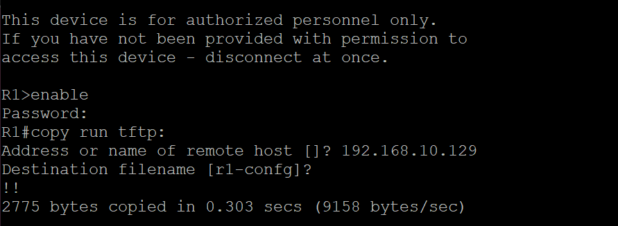
Using banner motd, create a banner to deter unauthorized users from logging on to Router R1.
Create an ACL to protect access to R1
Using a standard ACL, permit only the Linux-Mgmt Server (192.168.10.129) to access via SSH Router R1. Make sure to log all denied traffic and successful entries.
Configure NTP on Router R1
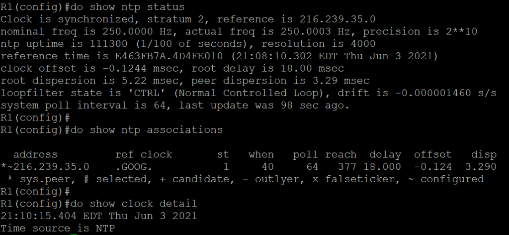
Set Router R1 to use Google’s Public NTP server. Verify that the Router can ping the server “time1.google.com”. Set the time zone to your appropriate time zone.
Verify NTP
Verify that an NTP server is configured and that the time source is from the NTP server. Note* Clock synchronization make take a few minutes to appear as synchronized.
Configure SNMPv3 on R1
Create a new SNMPv3 group named ‘network-admin’. Set the group to use the ‘AuthPriv’ security level. Create a SNMPv3 user ‘snmpadmin’ and assign to the newly created ‘network-admin’ group. Set the authentication protocol to SHA and the privacy encryption algorithm to AES 128. Verify the user was properly created by using ‘show snmp user’.
Configure password and add new user on Sw1
Configure an enable password. Create a new user with a secret password. Using banner motd, create a banner to deter unauthorized users from logging on to Switch Sw1.
Assign an IP to Sw1
Assign an IP from the Out-of-band Management VLAN. Add a default route to the VLANs gateway address. Verify connectivity by pinging the gateway and user device from Users VLAN.
Configure a domain name
Assign a domain “mylab.local” to the Switch Sw1.
Configure SSH
Generate a RSA key. Set the modulus bits to 2048. Make sure you use SSH version 2.
Configure ACL to protect access to Sw1
Using a standard ACL, permit only the Linux-Mgmt Server (192.168.10.129) to access via SSH Switch Sw1. Make sure to log all denied traffic and successful entries.
Configure NTP on Switch Sw1
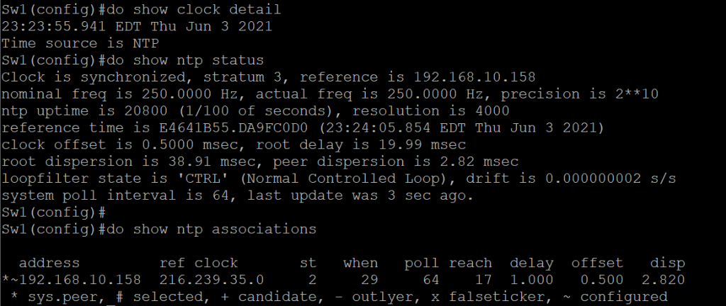
Set Switch Sw1 to use Router R1 Management IP. Set the timezone to your appropriate timezone.
Verify NTP
Verify that an NTP server is configured and that the time source is from the NTP server. Note* Clock synchronization make take a few minutes to appear as synchronized.
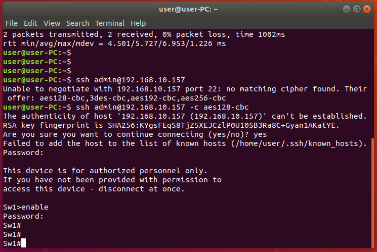
Verify connectivity to Sw-1
Verify the connectivity from the Linux-Mgmt workstation to the Switch Sw-1 using SSH.
For the following portion of the lab, we will need to provide internet access to the Linux-Mgmt workstation. In the previous lab, we did not allow VLAN 30 access to the internet. Now we will need to permit internet access in order to install the needed applications and updates. In order to do so, we will need to make a couple of changes to the Router to permit the traffic.
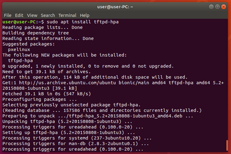
Install TFTP on Ubuntu
Using the following command “sudo apt install tftpd-hpa”, install tftpd-hpa service.
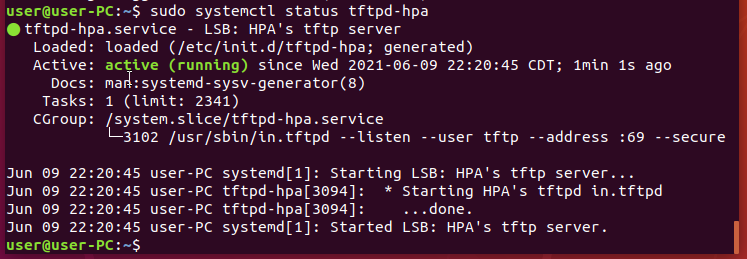
Verify TFTP service is active
Using the following command “sudo systemctl status tftpd-hpa”, to verify if the service is active.
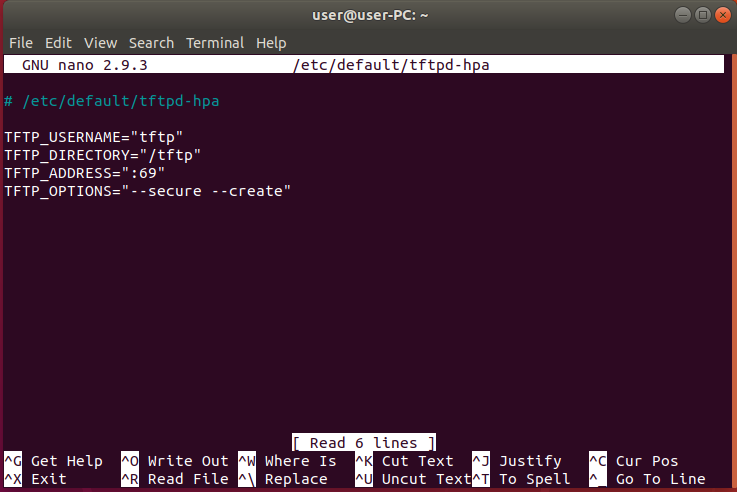
Edit tftpd-hpa configuration file
We need to edit a couple of things in order to get tftp running properly and allow our cisco devices to save their configs. Use the following command “sudo nano /etc/default/tftpd-hpa”.
We will need to add –create in TFTP_OPTIONS because that gives us the ability to add new files. Without the –create option, you won’t be able to create or upload new files to the TFTP server. In addition, we will change the directory of the tftp server to “/tftp”.
TFTP_USERNAME=”tftp”
TFTP_DIRECTORY=”/tftp”
TFTP_ADDRESS=”:69″
TFTP_OPTIONS=”–secure –create”
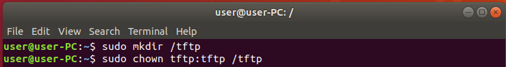
Make the new TFTP directory
Now that we have changed the tftp directory to “/tftp” we will need to create that directory as it doesn’t exist. Use the following command in order to create the directory “sudo mkdir /tftp”.
Permit TFTP service to write to the directory
In order to allow tftp service to write the directory, we will change the ownership of the directory and this will allow the tftp service to permit it to write to the directory. Use the following command “sudo chown tftp:tftp /tftp”.
Restart the TFTP server
In order for the changes to take we will need to restart the service. Enter the following command “sudo systemctl restart tftpd-hpa” this will restart the service.
From Router R1 copy configs
Go back to the router and using the “copy run tftp:” command copy the running-config to the server.
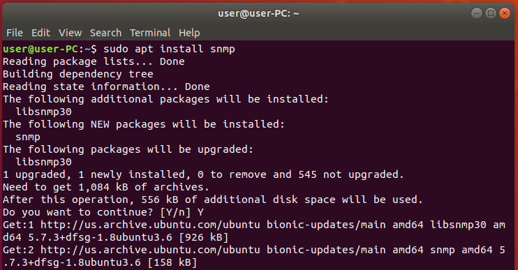
Install SNMP on Ubuntu
Using the following command “sudo apt install snmp”, to install SNMP on the linux workstation.
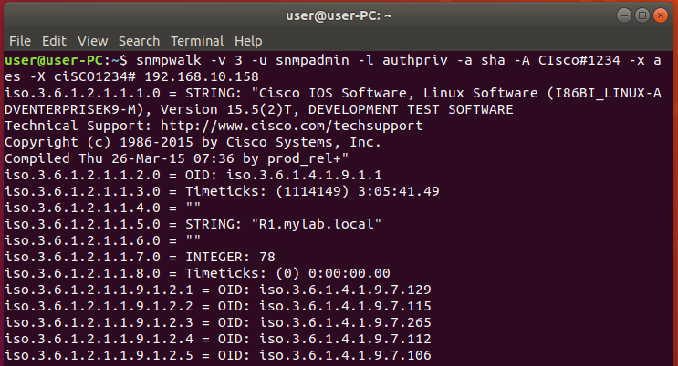
Test SNMP configurations
Using the following SNMP walk command “snmpwalk -v 3 -u snmpadmin -l authPriv -a sha -A CIsco#1234 -x aes -X ciSCO1234# 192.168.10.158” in order to verify that SNMP was properly configured on the router.
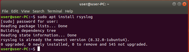
Install rsyslog on Ubuntu
Using the following command to install rsyslog “sudo apt install rsyslog”.
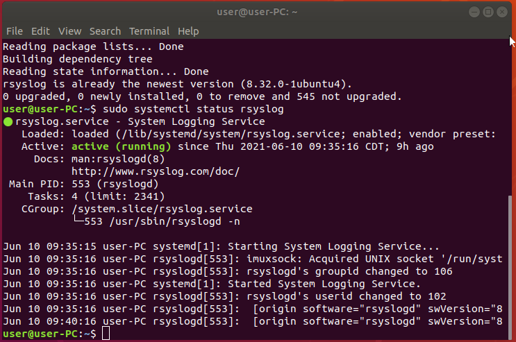
Verify the rsyslog service is running
To verify that rsyslog service is running on the server, use the following command “sudo systemctl status rsyslog”.
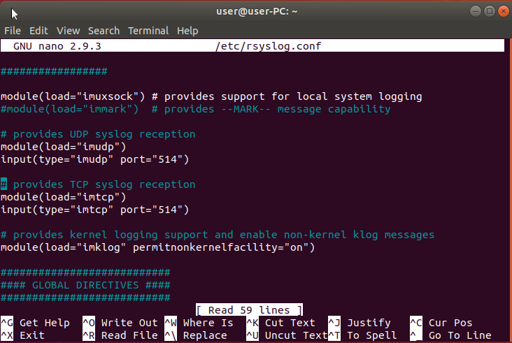
Configure rsyslog to run in Server mode
Edit the rsyslog config file using nano, do this by entering the following command “sudo nano /etc/rsyslog.conf”. Once the file is loaded look for the following lines and un-comment them by removing the ‘#’ symbol in front of the line.
module(load="imudp")
input(type="imudp" port="514")

module(load="imtcp")
input(type="imtcp" port="514")
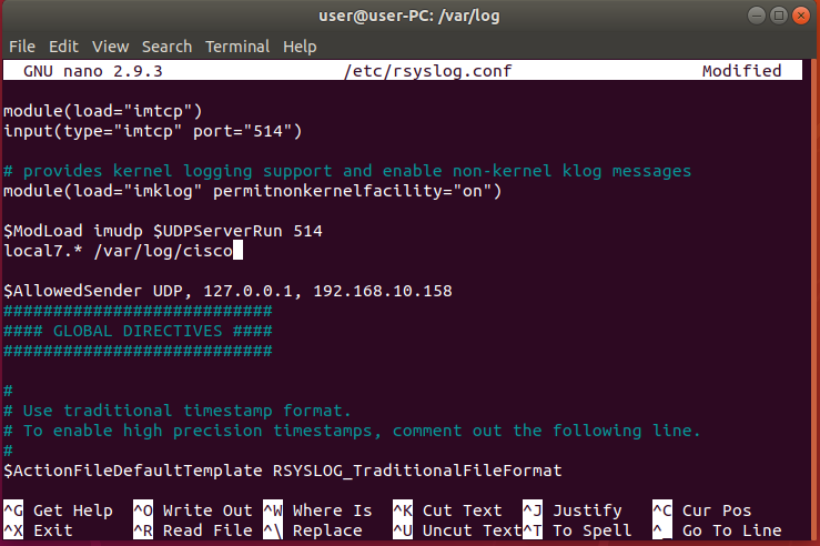
Create remote-incoming-logs template
Create a new template for receiving remote messages and add it just before GLOBAL DIRECTIVES. Enter the following lines.
$ModLoad imudp $UDPServerRun 514
local7.* /var/log/cisco

$AllowedSender UDP, 127.0.0.1, 192.168.10.158
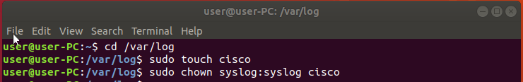
Create the file ‘cisco’
Create the file so that it may receive the data by using the following command “sudo touch cisco” while in the ‘/var/log/’ directory. If you are not in said directory make sure you change to the appropriate directory by using the cd command “cd /var/log/”.
Configure on R1 Syslog
Send the Syslog data to the Linux-Mgmt workstation 192.168.10.129. Add the source interface. Make sure to log user info, and set the logging severity level to receive informational level 6. Add the hostname as the origin-id so that the Syslog data sent will display the hostname of the router.
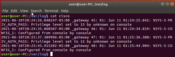
Verify the Syslog data on Server
Using cat followed by the filename display the contents of the Syslog data received by the server.
Here’s a video of me doing this particular lab. Catch more like these on my Youtube Channel.