Cisco ACL lab

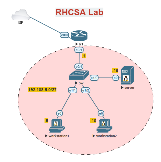
In this lab, we will run through the process of setting up a small network. We will use this network to show the different types of ACLs. We will start by using a standard named ACL in order to allow traffic to use NAT (PAT) to permit our workstation LAN network to access the internet. We will then create an extended network to permit web traffic but block others.


Change hostname Rtr-1
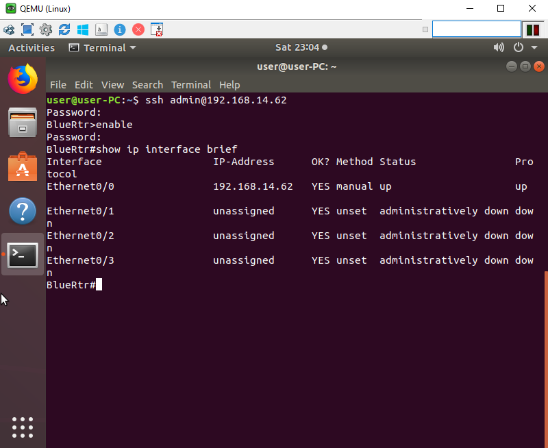
Access the router and change the hostname to ‘Rtr-1’. Configure the router to use Google’s DNS IP ‘8.8.8.8’.

Router>enable
Router#configure terminal
Enter configuration commands, one per line.  End with CNTL/Z.
Router(config)#hostname Rtr-1
Rtr-1(config)#ip domain-lookup
Rtr-1(config)#ip name-server 8.8.8.8

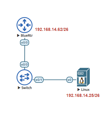
Configure Rtr-1 Interfaces
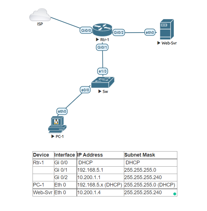
Configure each interface of Rtr-1 as they appear in the table above.

Rtr-1(config)#interface Gi0/0
Rtr-1(config-if)#ip address dhcp
Rtr-1(config-if)#no shutdown
Rtr-1(config-if)#exit
Rtr-1(config)#interface Gi0/1
Rtr-1(config-if)#ip address 192.168.5.1 255.255.255.0
Rtr-1(config-if)#no shutdown
Rtr-1(config-if)#exit
Rtr-1(config)#interface Gi0/2
Rtr-1(config-if)#ip address 10.200.1.1 255.255.255.240
Rtr-1(config-if)#no shutdown
Rtr-1(config-if)#exit
Rtr-1(config)#

Create a DHCP server on Router 1 name it Workstation-LAN
Setup a DHCP Pool named Workstation-LAN. Set the network as 192.168.5.0/24. Configure the DNS server to use Google’s DNS server IP address ‘8.8.8.8’. Set the gateway as the IP assigned to interface Gi 0/1. Reserve the first 25 IPs and the last 55 IPs.

Rtr-1(config)#ip dhcp pool Workstation-LAN
Rtr-1(dhcp-config)#network 192.168.5.0 255.255.255.0
Rtr-1(dhcp-config)#default-router 192.168.5.1
Rtr-1(dhcp-config)#dns-server 8.8.8.8
Rtr-1(dhcp-config)#exit
Rtr-1(config)#ip dhcp excluded-address 192.168.5.1 192.168.5.25
Rtr-1(config)#ip dhcp excluded-address 192.168.5.201 192.168.5.255


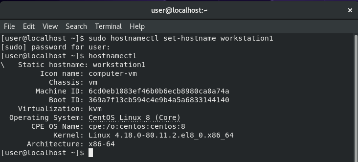
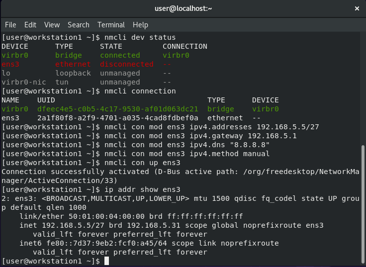
Set up PC-1 to a Dynamic IP address
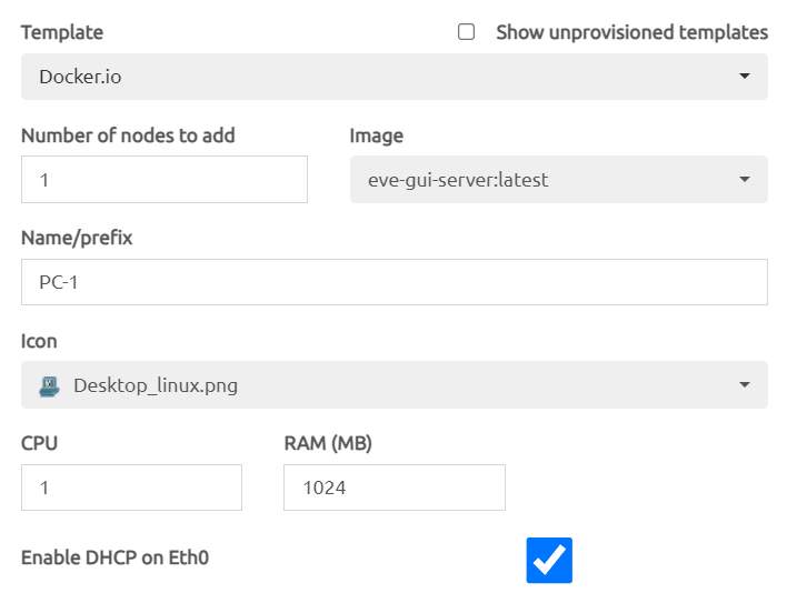
I am using a Docker container in this lab, but you can use a Linux VM, Windows VM, or even a Virtual PC. If you are using the Docker container in EVE-NG make sure to Enable DHCP on Eth 0 is checked in the configuration window.

Set up Web-Svr as a Static IP
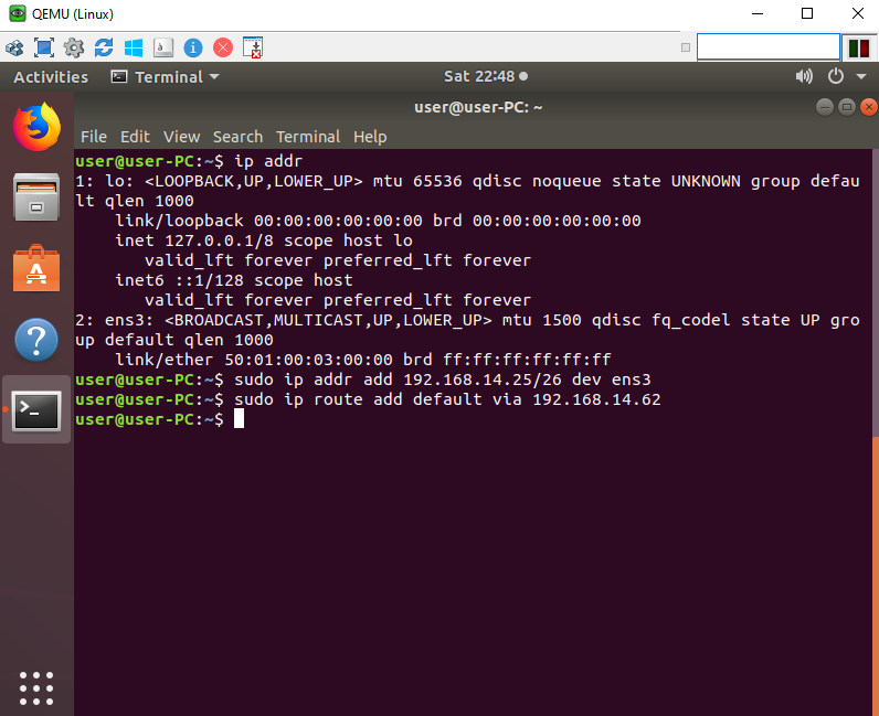
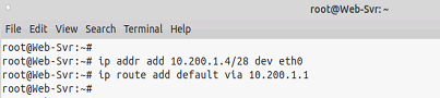
Configure the Web Server to use a static IP as it appears in the table above. Using a terminal configure the IP address. In this lab, I used a Docker container you can use a Linux VM, Windows VM, or a Virtual PC.

root@Web-Svr:~# ip addr add 10.200.1.4/28 dev eth0
root@Web-Svr:~# ip route add default via 10.200.1.1

Configure NAT Overload (PAT) on Rtr-1
Define the inside and outside interfaces on Rtr-1. Create a standard named ACL, using the name ‘NAT-ACL’. Permit the Workstation-LAN on the ACL. Set the ACL ‘NAT-ACL’ as the inside source and set the outside interface to overload.

Rtr-1(config)#interface Gi0/0
Rtr-1(config-if)#ip nat outside
Rtr-1(config-if)#exit
Rtr-1(config)#interface Gi0/1
Rtr-1(config-if)#ip nat inside
Rtr-1(config-if)#exit
Rtr-1(config)#ip access-list standard NAT-ACL
Rtr-1(config-std-nacl)#permit 192.168.5.0 0.0.0.255
Rtr-1(config-std-nacl)#exit
Rtr-1(config)#ip nat inside source list NAT-ACL interface Gi0/0 overload

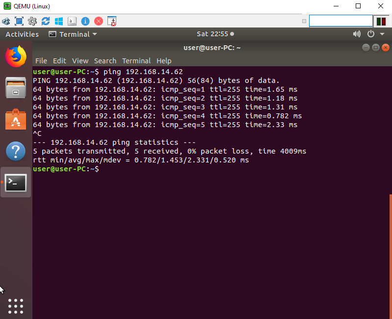
Verify PC-1 can access internet websites
Open an RDP session to PC-1 and open a web browser and connect to any website to verify connectivity.

Start a simple web server
If you are using Docker Container in Eve-NG Pro ‘Gui-Server’ as I did you will not need to follow these instructions. If you are using a Linux VM add the following commands in the Linux terminal.

sudo apt update
sudo apt install apache2

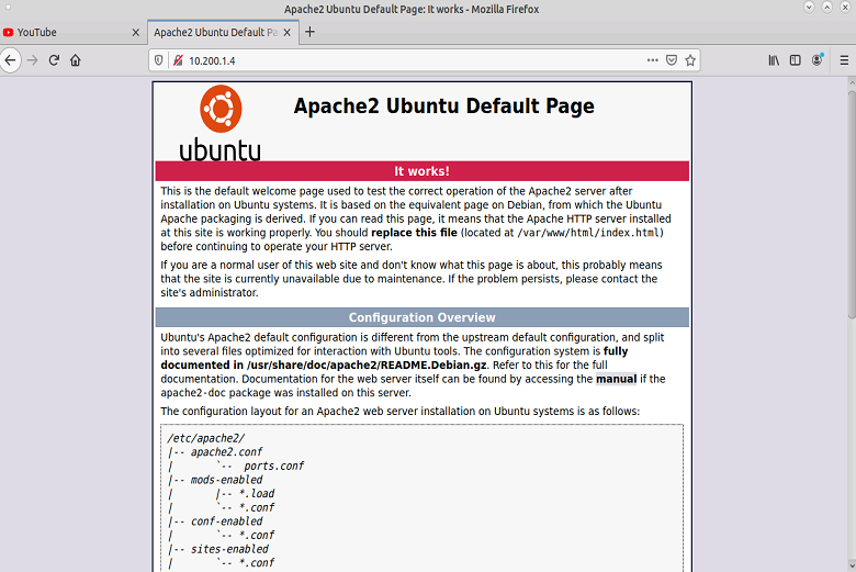
After entering those commands you should be able to open the PC-1 web browser and access the apache webserver by typing the Web-Svr IP in the search bar of the browser like so ‘http://10.200.1.4’.

Start a Python SimpleHTTP Server on port 8080
Return back to the Web-Svr terminal and enter the following command in order to start an additional webserver on the Web-Svr.

root@Web-Svr:~# python -m SimpleHTTPServer 8080
Serving HTTP on 0.0.0.0 port 8080 ...

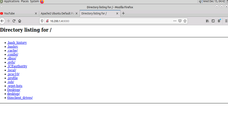
After entering those commands you should be able to open the PC-1 web browser and access the SimpleHTTPServer app using port 8080 and the IP address of the Web-Svr.

Create an extended ACL to block PC-1 access to port 80 but continue to permit 8080
Access Rtr-1 and configure an extended ACL using the access-list number 104. Assign the ACL to the appropriate interface. Remember the ACL created should be configured closer to the source.

Rtr-1(config)#ip access-list extended 104
Rtr-1(config-ext-nacl)#permit tcp host 192.168.5.26 host 10.200.1.4 eq 8080
Rtr-1(config-ext-nacl)#deny tcp host 192.168.5.26 host 10.200.1.4 eq 80
Rtr-1(config-ext-nacl)#exit
Rtr-1(config)#interface Gi0/1
Rtr-1(config-if)#ip access-group 104 in

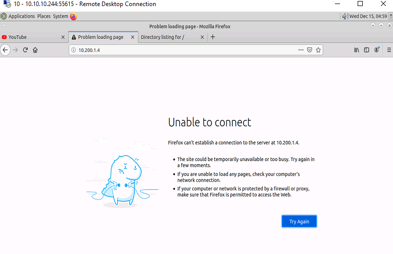
Verify that PC-1 no longer has access to Port 80 of the Web-Svr

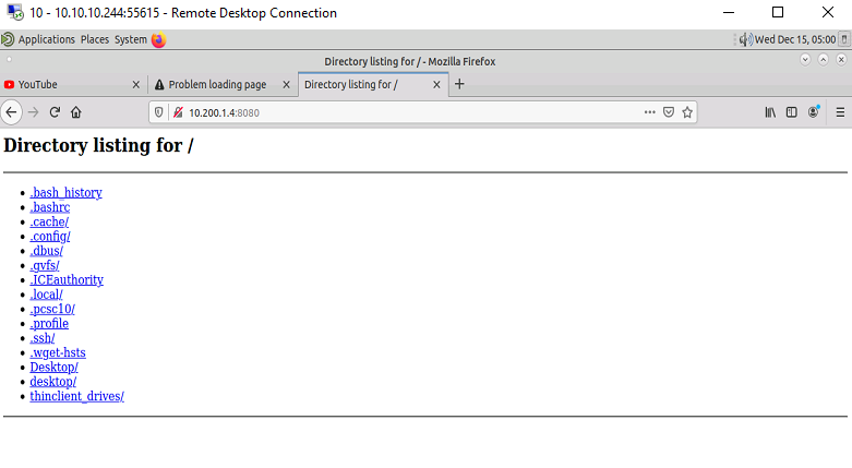
Verify the PC-1 still has access to port 8080 of the Web-Svr

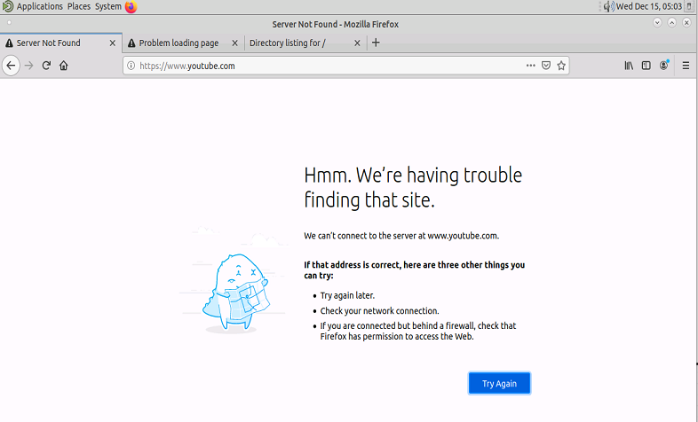
Uh oh PC-1 No longer has access to the internet.

Fix the ACL so that PC-1 regains Internet Access
Change the ACL to permit all other traffic before the implicit deny.

Rtr-1(config)#ip access-list extended 104
Rtr-1(config-ext-nacl)#permit ip any any
Rtr-1(config-ext-nacl)#end

Verify that PC-1 can now access the internet after the ACL changes

You have completed the lab.

Managing Cisco Devices

Managing your Cisco Switches and Routers are essential to maintaining a healthy network. They’re numerous protocols, features, and technologies used throughout data centers across the globe to assist network administrators to support their network. While it would be hard to show everything in a lab all the technologies we can concentrate on core network protocols that are essential to managing your devices. In this lab, we are going to use some well-known protocols and features: NTP, SNMPv3, Syslog, ACLs, and TFTP.

Using the previously configured lab “GRE Tunnel Lab” we are going to expand and configure the Washington DC site to use these technologies. I will also use an Ubuntu server to assist in using these tools in order to manage the devices.

Configure a banner
Using banner motd, create a banner to deter unauthorized users from logging on to Router R1.

R1>enable
Password:
R1#configure terminal
Enter configuration commands, one per line.  End with CNTL/Z.
R1(config)#banner motd #
Enter TEXT message.  End with the character '#'.
This device is for authorized personnel only.
If you have not been provided with permission to
access this devices - disconnect at once.

#
R1(config)#

Create an ACL to protect access to R1
Using a standard ACL, permit only the Linux-Mgmt Server (192.168.10.129) to access via SSH Router R1. Make sure to log all denied traffic and successful entries.

R1(config)#ip access-list standard 5
R1(config-std-nacl)#remark Permitted-Devices-VTY
R1(config-std-nacl)#permit 192.168.10.129 log
R1(config-std-nacl)#deny any log
R1(config-std-nacl)#exit
R1(config)#line vty 0 4
R1(config-line)#access-class 5 in
R1(config-line)#transport input ssh
R1(config-line)#exit
R1(config)#

Configure NTP on Router R1
Set Router R1 to use Google’s Public NTP server. Verify that the Router can ping the server “time1.google.com”. Set the time zone to your appropriate time zone.

R1(config)#do ping time1.google.com
Translating "time1.google.com"...domain server (8.8.8.8) [OK]

Type escape sequence to abort.
Sending 5, 100-byte ICMP Echos to 216.239.35.0, timeout is 2 seconds:
!!!!!
Success rate is 100 percent (5/5), round-trip min/avg/max = 17/18/19 ms
R1(config)#ntp server time1.google.com
R1(config)#clock timezone EDT -4
R1(config)#
*Jun  4 01:02:54.589: %SYS-6-CLOCKUPDATE: System clock has been updated from 20:02:54 EST Thu Jun 3 2021 to 21:02:54 EDT Thu Jun 3 2021, configured from console by console.

Verify NTP
Verify that an NTP server is configured and that the time source is from the NTP server. Note* Clock synchronization make take a few minutes to appear as synchronized.

Configure SNMPv3 on R1
Create a new SNMPv3 group named ‘network-admin’. Set the group to use the ‘AuthPriv’ security level. Create a SNMPv3 user ‘snmpadmin’ and assign to the newly created ‘network-admin’ group. Set the authentication protocol to SHA and the privacy encryption algorithm to AES 128. Verify the user was properly created by using ‘show snmp user’.

R1(config)#snmp-server group network-admin v3 ?
  auth    group using the authNoPriv Security Level
  noauth  group using the noAuthNoPriv Security Level
  priv    group using SNMPv3 authPriv security level

R1(config)#snmp-server group network-admin v3 priv
R1(config)#snmp-server user snmpadmin network-admin v3 auth sha CIsco#1234 priv aes 128 ciSCO1234#
R1(config)#
R1(config)#do show snmp user

User name: snmpadmin
Engine ID: 800000090300AABBCC000100
storage-type: nonvolatile        active
Authentication Protocol: SHA
Privacy Protocol: AES128
Group-name: network-admin

Configure password and add new user on Sw1
Configure an enable password. Create a new user with a secret password. Using banner motd, create a banner to deter unauthorized users from logging on to Switch Sw1.

Sw1>enable
Sw1#configure terminal
Enter configuration commands, one per line.  End with CNTL/Z.
Sw1(config)#enable secret cisco
Sw1(config)#username admin secret $trongP@$$word1234
Sw1(config)#banner motd #
Enter TEXT message.  End with the character '#'.
This device is for authorized personnel only.
If you have not been provided with permission to
access this device - disconnect at once.
#

Assign an IP to Sw1
Assign an IP from the Out-of-band Management VLAN. Add a default route to the VLANs gateway address. Verify connectivity by pinging the gateway and user device from Users VLAN.

Sw1(config)#interface vlan 30
*Jun  4 02:27:36.229: %LINEPROTO-5-UPDOWN: Line protocol on Interface Vlan30, changed state to down
Sw1(config-if)#ip address 192.168.10.157 255.255.255.224
Sw1(config-if)#no shutdown
Sw1(config-if)#exit
Sw1(config)#ip route 0.0.0.0 0.0.0.0 192.168.10.158
Sw1(config)#do ping 192.168.10.158
Type escape sequence to abort.
Sending 5, 100-byte ICMP Echos to 192.168.10.158, timeout is 2 seconds:
.!!!!
Success rate is 80 percent (4/5), round-trip min/avg/max = 1/1/1 ms
Sw1(config)#do ping 192.168.10.1
Type escape sequence to abort.
Sending 5, 100-byte ICMP Echos to 192.168.10.1, timeout is 2 seconds:
!!!!!
Success rate is 100 percent (5/5), round-trip min/avg/max = 1/1/1 ms

Configure a domain name
Assign a domain “mylab.local” to the Switch Sw1.

Sw1(config)#ip domain-name mylab.local

Configure SSH
Generate a RSA key. Set the modulus bits to 2048. Make sure you use SSH version 2.

Sw1(config)#crypto key generate rsa
The name for the keys will be: Sw1.mylab.local
Choose the size of the key modulus in the range of 360 to 4096 for your
  General Purpose Keys. Choosing a key modulus greater than 512 may take
  a few minutes.

How many bits in the modulus [512]: 2048
% Generating 2048 bit RSA keys, keys will be non-exportable...
[OK] (elapsed time was 10 seconds)

Sw1(config)#
*Jun  4 02:55:56.917: %SSH-5-ENABLED: SSH 1.99 has been enabled
Sw1(config)#ip ssh version 2

Configure ACL to protect access to Sw1
Using a standard ACL, permit only the Linux-Mgmt Server (192.168.10.129) to access via SSH Switch Sw1. Make sure to log all denied traffic and successful entries.

Sw1(config)#ip access-list standard 5
Sw1(config-std-nacl)#remark Permitted-Devices-VTY
Sw1(config-std-nacl)#permit 192.168.10.129 log
Sw1(config-std-nacl)#deny any log
Sw1(config-std-nacl)#exit
Sw1(config)#line vty 0 4
Sw1(config-line)#access-class 5 in
Sw1(config-line)#transport input ssh
Sw1(config-line)#login local
Sw1(config-line)#exit
Sw1(config)#

Configure NTP on Switch Sw1
Set Switch Sw1 to use Router R1 Management IP. Set the timezone to your appropriate timezone.

Sw1(config)#ntp server 192.168.10.158
Sw1(config)#clock timezone EDT -4
Sw1(config)#
*Jun  4 03:20:40.848: %SYS-6-CLOCKUPDATE: System clock has been updated from 22:20:40 EST Thu Jun 3 2021 to 23:20:40 EDT Thu Jun 3 2021, configured from console by console.

Verify NTP
Verify that an NTP server is configured and that the time source is from the NTP server. Note* Clock synchronization make take a few minutes to appear as synchronized.

Verify connectivity to Sw-1
Verify the connectivity from the Linux-Mgmt workstation to the Switch Sw-1 using SSH.

For the following portion of the lab, we will need to provide internet access to the Linux-Mgmt workstation. In the previous lab, we did not allow VLAN 30 access to the internet. Now we will need to permit internet access in order to install the needed applications and updates. In order to do so, we will need to make a couple of changes to the Router to permit the traffic.

R1(config)#ip access-list standard 10
R1(config-std-nacl)#30 permit 192.168.10.128 0.0.0.31
R1(config-std-nacl)#exit
R1(config)#
R1(config)#interface ethernet 0/0.30
R1(config-subif)#ip nat inside
R1(config-subif)#exit
R1(config)#

Install TFTP on Ubuntu
Using the following command “sudo apt install tftpd-hpa”, install tftpd-hpa service.

Verify TFTP service is active
Using the following command “sudo systemctl status tftpd-hpa”, to verify if the service is active.


Edit tftpd-hpa configuration file
We need to edit a couple of things in order to get tftp running properly and allow our cisco devices to save their configs. Use the following command “sudo nano /etc/default/tftpd-hpa”.

We will need to add –create in TFTP_OPTIONS because that gives us the ability to add new files. Without the –create option, you won’t be able to create or upload new files to the TFTP server. In addition, we will change the directory of the tftp server to “/tftp”.
TFTP_USERNAME=”tftp”
TFTP_DIRECTORY=”/tftp”
TFTP_ADDRESS=”:69″
TFTP_OPTIONS=”–secure –create”

Make the new TFTP directory
Now that we have changed the tftp directory to “/tftp” we will need to create that directory as it doesn’t exist. Use the following command in order to create the directory “sudo mkdir /tftp”.

Permit TFTP service to write to the directory
In order to allow tftp service to write the directory, we will change the ownership of the directory and this will allow the tftp service to permit it to write to the directory. Use the following command “sudo chown tftp:tftp /tftp”.

Restart the TFTP server
In order for the changes to take we will need to restart the service. Enter the following command “sudo systemctl restart tftpd-hpa” this will restart the service.

From Router R1 copy configs
Go back to the router and using the “copy run tftp:” command copy the running-config to the server.

Install SNMP on Ubuntu
Using the following command “sudo apt install snmp”, to install SNMP on the linux workstation.

Test SNMP configurations
Using the following SNMP walk command “snmpwalk -v 3 -u snmpadmin -l authPriv -a sha -A CIsco#1234 -x aes -X ciSCO1234# 192.168.10.158” in order to verify that SNMP was properly configured on the router.

Install rsyslog on Ubuntu
Using the following command to install rsyslog “sudo apt install rsyslog”.

Verify the rsyslog service is running
To verify that rsyslog service is running on the server, use the following command “sudo systemctl status rsyslog”.

Configure rsyslog to run in Server mode
Edit the rsyslog config file using nano, do this by entering the following command “sudo nano /etc/rsyslog.conf”. Once the file is loaded look for the following lines and un-comment them by removing the ‘#’ symbol in front of the line.

module(load="imudp")
input(type="imudp" port="514")

module(load="imtcp")
input(type="imtcp" port="514")

Create remote-incoming-logs template
Create a new template for receiving remote messages and add it just before GLOBAL DIRECTIVES. Enter the following lines.

$ModLoad imudp $UDPServerRun 514
local7.* /var/log/cisco

$AllowedSender UDP, 127.0.0.1, 192.168.10.158

Create the file ‘cisco’
Create the file so that it may receive the data by using the following command “sudo touch cisco” while in the ‘/var/log/’ directory. If you are not in said directory make sure you change to the appropriate directory by using the cd command “cd /var/log/”.

Configure on R1 Syslog
Send the Syslog data to the Linux-Mgmt workstation 192.168.10.129. Add the source interface. Make sure to log user info, and set the logging severity level to receive informational level 6. Add the hostname as the origin-id so that the Syslog data sent will display the hostname of the router.

R1(config)#logging host 192.168.10.129
R1(config)#
Jun 11 00:42:22.555: %SYS-6-LOGGINGHOST_STARTSTOP: Logging to host 192.168.10.129 port 514 started - CLI initiated
R1(config)#logging source-interface ethernet 0/0.30
R1(config)#logging userinfo
R1(config)#logging trap 6
R1(config)#logging origin-id hostname
R1(config)#logging on

Verify the Syslog data on Server
Using cat followed by the filename display the contents of the Syslog data received by the server.

Here’s a video of me doing this particular lab. Catch more like these on my Youtube Channel.

RHCSA Lab

RedHat Certified System Adminitrator is a systems administrator that has proven to have the sufficient knowledge to maintain and manage a Red Hat Linux enterprise environment. Since college, I have used Linux on and off. At work a few years back I was given the opportunity to take RHSA 1 and 2 courses. Each course is a week long course of labs and direct instruction from a certified RedHat instructor. I took the RHCSA 200 exam at the culmination of Red Hat classes. I didn’t pass, but thats ok. I always wanted to go back and study. So here is my chance of self-study. This will be an on going effort where I can test common tasks that are needed to pass the practical exam.

So as I complete each lab I will link back to this page. For the first lab lets get the three on the same network an talking with each other.

Task 1:
Configure the hostname on workstation1 using hostnamectl.

$ sudo hostnamectl set-hostname workstation1
$ hostnamectl

Task 2:
Configure the IP address, Gateway, DNS using nmcli. To list the currently active interfaces use the “nmcli connection” command.

2-a: Assign IPv4 address.

$ nmcli con mod ens3 ipv4.addresses 192.168.5.5/27

2-b: Set the gateway address.

$ nmcli con mod ens3 ipv4.gateway 192.168.5.1

2-c: Configure the DNS.

$ nmcli con mod ens3 ipv4.dns "8.8.8.8"

2-d: Set the interface as static.

$ nmcli con mod ens3 ipv4.method manual

2-e: Activate the network interface.

$ nmcli con up ens3 

Task 3:
Use ping to confirm the connection.

Now you can repeat the process with workstation2 and server VMs.

Lab: Configure SSH

Connecting via SSH is essential in today’s networks. Cisco devices are not automatically capable to use SSH. It has to be enabled and configured. SSH (Secure Shell) is a secure method to remote access network devices as it includes both authentication and encryption. To configure SSH you will need an IOS image that supports crypto features.

This lab is a basic SSH configuration. I will be using a Ubuntu 18.04 image as a workstation to connect to the router.

When configuring SSH on a Cisco router you will need to make sure the router has a host name. It will also need a domain name. An RSA key will need to be generated, user will need to be created on the Cisco router and finally after SSH is enabled you will need to configure the VTY lines to allow the connection to occur.

Task 1:
Configure the host name on the router.

Router>
Router>enable
Router#configure terminal
Enter configuration commands, one per line.  End with CNTL/Z.
Router(config)#hostname BlueRtr
BlueRtr(config)#

Task 2:
Configure a domain name.

BlueRtr(config)#ip domain-name joelrivera.com.local

Task 3:
Generate a RSA key. I recommend 2048 or greater when configuring the modulus bits. Make sure you use SSH version 2.

BlueRtr(config)#crypto key generate rsa
The name for the keys will be: BlueRtr.joelrivera.com.local
Choose the size of the key modulus in the range of 360 to 4096 for your
  General Purpose Keys. Choosing a key modulus greater than 512 may take
  a few minutes.

How many bits in the modulus [512]: 2048
% Generating 2048 bit RSA keys, keys will be non-exportable...
[OK] (elapsed time was 5 seconds)

BlueRtr(config)#
*Apr  5 02:57:18.367: %SSH-5-ENABLED: SSH 1.99 has been enabled
BlueRtr(config)#ip ssh version 2

Task 4:
Create a user with a password and an enable password. Make sure you use your own password and that you follow your companies security policies when creating a user account.

BlueRtr(config)#username admin secret $TrongP@$$word1234
BlueRtr(config)#enable secret cisco

Task 5:
Now that SSH is enabled we need to configure the VTY lines to allow the SSH connection through.

BlueRtr(config)#line vty 0 4
BlueRtr(config-line)#transport input ssh
BlueRtr(config-line)#login local
BlueRtr(config-line)#exit

Task 6:
Configure the ip address of the LAN connection of the router.

BlueRtr(config)#interface ethernet 0/0
BlueRtr(config-if)#ip address 192.168.14.62 255.255.255.192
BlueRtr(config-if)#no shutdown
BlueRtr(config-if)#end

Once the configuration is complete, now we need to test. I am using an Ubuntu 18.04 image. In this lab the most important part is to configure the device to be on the same network. In reality, SSH will work when connecting from an outside network so long as the device has a route to the network device and that it is not blocked from an ACL or Firewall.

To configure a static IP address in Ubuntu 18.04, we will need to identify the physical named interface on the device. To find out the proper name type “ip addr“. Once identified in my case its ens3, Enter the following command to statically configure the IP address “sudo ip addr add 192.168.14.25/26 dev ens3“. To configure the gateway enter the following command “sudo ip route add default via 192.168.14.62“.

Ping the gateway to confirm the device can ping the router.

Finally let’s test the SSH connection by typing “ssh admin@192.168.14.62“. Type in the user’s password when requested, and the enable password as well. Congratulations you have configured and connected to a router via SSH.