HSRP stands for Hot Standby Routing Protocol.
We use HSRP for gateway redundancy. Our goal is for our network to have a transparent
failover in order to achieve High Availability. We want our host to auto-magically choose a next hop
for routing IP traffic in order to recover if one of our routers were to fail. So how does HSRP work?
Well, when HSRP is configured on a network segment it provides a virtual MAC Address and an IP Address that is shared among a group of routers that are running HSRP. This virtual IP address belongs to the HSRP group, and the routers that are in this group will either be designated as the active router or be placed on Standby. So when HSRP detects that the designated active router fails, the selected standby router will assume control of the MAC and IP addresses of the HSRP group. A new standby router is also selected once the newly designated active router assumes control.
Devices that are running HSRP will send and receive multicast User Datagram Protocol (UDP) based hello packets to detect router failure.
An HSRP group consists of two or more routers running HSRP. HSRP uses a priority scheme to
determine which HSRP-configured router is to be the default active router. When configuring HSRP we assign a priority to the routers. The router with the highest priority in the group will be the default active router. The default priority value is 100, so if you configure a router to be higher than the default and the other router(s) are left at the default value, then that router will be chosen as the default active router. If the priority is the same, then the switch with the highest IP address will become the active device.
Configure the IP address assigned to the VPC device.
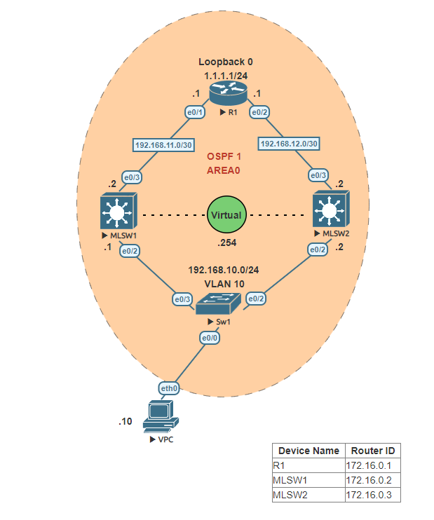
Configure Router 1
Properly name the device to the hostname shown in the network diagram above. Assign the appropriate IP addresses to each of the interfaces.
Configure both of the multilayer switches MLSW1 & MLSW2
Properly name the device to the hostname shown in the network diagram above. Assign the appropriate IP address to the interface connected to R1. Name VLAN 10 to “v10-Host”. Assign the correct IP address to VLAN 10. Assign the interface connected to the Layer 2 switch to VLAN 10.
Configure OSPF on R1, MLSW1 & MLSW2
To set up interconnectivity between all the networks, let’s use OSPF. Using OSPF process ID 1, assign the appropriate router-id to each device and add all the local networks of R1, MLSW1 & MLSW2. The OSPF area ID should be set to 0.
Enable HSRP on MLSW1 & MLSW2
Assign the VLAN 10 interface on both MLSW1 & MLSW2 to HSRP group 1 using the Virtual IP address 192.168.10.254. Leave the default HSRP priority to 100 on both switches.
Using show commands determine which switch is set to Active
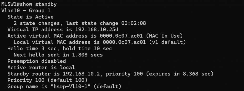
Either using the show command “show standby” or “show standby brief” on either of the switches determine which is set to active and which is set to standby. “show standby” is verbose and shows more information.
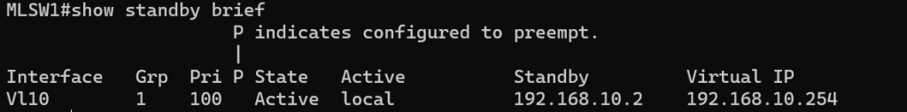
The show command “show standby brief” provides similar information in a shorter form. In the “standby brief” table the State column will indicate whether it’s active or standby, you can see in the image below that MLSW1 has been set to Active.
Set the priority higher than the default on either switch
Choose either MLSW1 or MLSW2 and set the priority to 150. In this example, I set MLSW2 to priority 150.
Run the show command “show standby brief” on the switch that you increased the priority of.
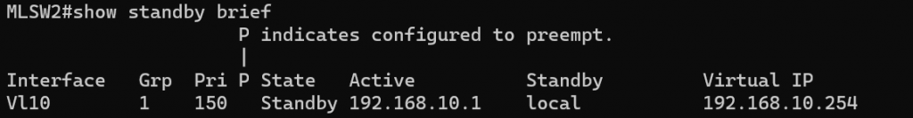
You may be wondering why if changing the priority to a higher priority, why hasn’t that switch now become the Active switch? We will need to use preempt in order for the switch to become the new Active switch. By default, preemption will take effect immediately but it might be a good idea to use a delay. If a router reboots it might need some time to “converge”. Maybe OSPF or EIGRP will need to form neighbor adjacencies or the spanning tree isn’t ready yet to unblock the ports. Therefore I am going to set the delay to a minimum of 60 seconds.
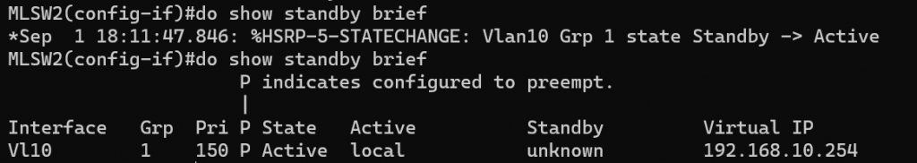
After a minute has passed recheck to see if now the switch has become the Active switch. You can see in the image below the Syslog message that indicates an HSRP state change to Active, and running the show command “show standby brief” confirms it.
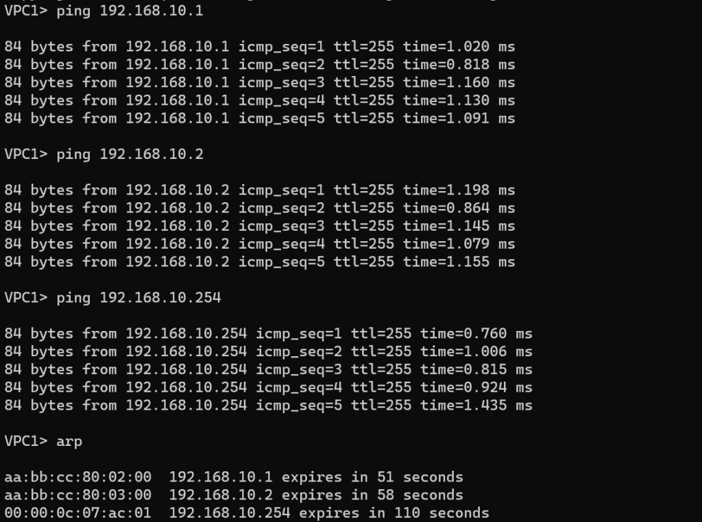
From the host pc “VPC1”, let’s ping the default gateway. Which should be the Virtual gateway IP address. After pinging the virtual gateway proceed to ping both MLSW1 & MLSW2 VLAN 10 IP addresses. Then run the arp command. As you can see the MAC addresses of the VLAN 10 interfaces are different from the virtual gateway MAC address.
By default, HSRP is pretty slow. MLSW1 is my standby router and it will wait for 10 seconds (hold time) before it will become active once MLSW2 fails. That means we’ll have 10 seconds of downtime… We can speed the standby timer up. Let’s change the Hello timer to 1 second and the hold timer for 4 seconds.
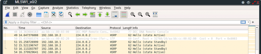
Using WireShark on MLSW2 Ethernet 0/2 interface you can see the HSRP Hello traffic. We see that this communication is done by using the multicast address 224.0.0.2.
There are two versions of HSRP and depending on the router or switch model you might have the option to use HSRP version 2. You can change the version by using the standby version command. Let’s change the HSRP version to version 2. On both MLSW1 and MLSW2 change the version to version 2.
In the table are some of the differences between HSRPv1 and HSRPv2
| HSRPv1 | HSRPv2 | |
| Group Numbers | 0 – 255 | 0 – 4095 |
| Virtual MAC address | 0000.0c07.acXX (XX = group number) | 0000.0c9f.fxxx (XXX = group number) |
| Multicast Address | 224.0.0.2 | 224.0.0.102 |
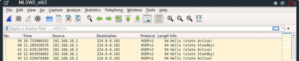
Now that we have changed the HSRP version, using Wireshark we can see that the Hello HSRP packet is using a different multicast address 224.0.0.102.
This concludes the HSRP lab. I hope you enjoyed it and learned from it.