GRE Tunnel Lab

I completed an example of this lab and posted the video on YouTube. You can view the video in the link below. I plan on posting more labs like the ones found on my blog on that channel. Please subscribe and leave a comment that you found the link through my blog.

Generic Routing Encapsulation (GRE) is a tunneling protocol that provides the ability of routers to transport packets of one protocol over another protocol. This is done by way of encapsulation. Encapsulation is the process of enclosing the data of a packet inside another packet. It also provides the ability to create virtual interfaces that can connect two different sites that are not in near proximity, and appear to be adjacent from each other. With this technology, we can use unicast, broadcast, and multicast communication over this virtual interface. Because multicast is allowed to be encapsulated through a GRE Tunnel we can use Interior Gateway Routing Protocols to exchange routes between the sites and yes even through the internet.

Configure Router R1
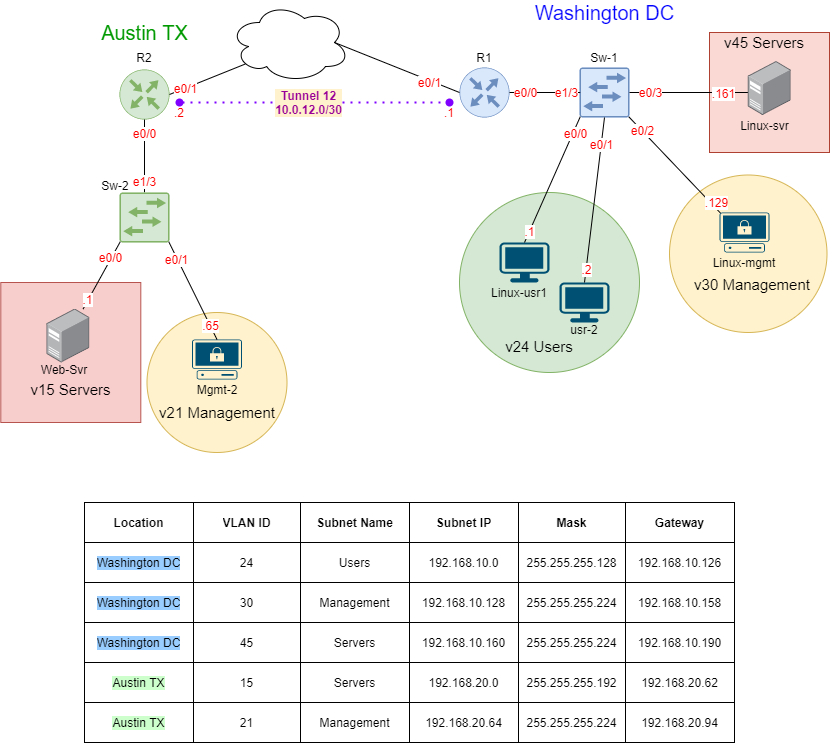
Set the hostname. Configure the interfaces and sub-interfaces ip addresses to match the table above. The Sub-Interfaces shall use encapsulation dot1q and the specific sub-interfaces should match the VLAN-ID. Set interface ethernet 0/1 to receieve its IP Address automatically using DHCP.

Router>enable
Router#configure terminal
Enter configuration commands, one per line.  End with CNTL/Z.
Router(config)#hostname R1
R1(config)#interface ethernet 0/0
R1(config-if)#no ip address
R1(config-if)#no shutdown
R1(config-if)#interface ethernet 0/0.24
R1(config-subif)#encapsulation dot1q 24
R1(config-subif)#ip address 192.168.10.126 255.255.255.128
R1(config-subif)#exit
R1(config)#interface ethernet 0/0.30
R1(config-subif)#encapsulation dot1q 30
R1(config-subif)#ip address 192.168.10.158 255.255.255.224
R1(config-subif)#exit
R1(config)#interface ethernet 0/0.45
R1(config-subif)#encapsulation dot1q 45
R1(config-subif)#ip address 192.168.10.190 255.255.255.224
R1(config-subif)#exit
R1(config)#interface ethernet 0/1
R1(config-if)#ip address dhcp
R1(config-if)#no shutdown
*May 22 02:19:43.849: %DHCP-6-ADDRESS_ASSIGN: Interface Ethernet0/1 assigned DHCP address 172.29.129.129, mask 255.255.255.0, hostname R1
R1(config-if)#exit

**Note: The IP address on the outbound interface (Ethernet 0/1) may also be configured manually if DHCP is not an option.

Configure Switch Sw1
Set the hostname. Create the VLANs (VLAN 24, 30, and 45) and assign the descriptive name as it appears in the table above. Configure the trunk using encapsulation dot1q and allow the VLANs created. Configure the access ports and assign the appropriate VLAN to the interface.

Switch>enable
Switch#configure terminal
Enter configuration commands, one per line.  End with CNTL/Z.
Switch(config)#hostname Sw1
Sw1(config)#vlan 24
Sw1(config-vlan)#name Users
Sw1(config-vlan)#exit
Sw1(config)#vlan 30
Sw1(config-vlan)#name Management
Sw1(config-vlan)#exit
Sw1(config)#vlan 45
Sw1(config-vlan)#name Servers
Sw1(config-vlan)#exit
Sw1(config)#interface ethernet 1/3
Sw1(config-if)#switchport trunk encapsulation dot1q
Sw1(config-if)#switchport mode trunk
Sw1(config-if)#switchport trunk allowed vlan 24,30,45
Sw1(config-if)#exit
Sw1(config)#interface ethernet 0/0
Sw1(config-if)#switchport mode access
Sw1(config-if)#switchport access vlan 24
Sw1(config-if)#exit
Sw1(config)#interface ethernet 0/1
Sw1(config-if)#switchport mode access
Sw1(config-if)#switchport access vlan 24
Sw1(config-if)#exit
Sw1(config)#interface ethernet 0/2
Sw1(config-if)#switchport mode access
Sw1(config-if)#switchport access vlan 30
Sw1(config-if)#exit
Sw1(config)#interface ethernet 0/3
Sw1(config-if)#switchport mode access
Sw1(config-if)#switchport access vlan 45
Sw1(config-if)#exit

Configure Router R2
Set the hostname. Configure the interfaces and sub-interfaces IP addresses to match the table above. The Sub-Interfaces shall use encapsulation dot1q and the specific sub-interfaces should match the VLAN-ID. Set interface ethernet 0/1 to receive its IP Address automatically using DHCP.

Router>enable
Router#configure terminal
Enter configuration commands, one per line.  End with CNTL/Z.
Router(config)#hostname R2
R2(config)#interface ethernet 0/0
R2(config-if)#no ip address
R2(config-if)#no shutdown
R2(config-if)#interface ethernet 0/0.15
R2(config-subif)#encapsulation dot1q 15
R2(config-subif)#ip address 192.168.20.62 255.255.255.192
R2(config-subif)#exit
R2(config)#interface ethernet 0/0.21
R2(config-subif)#ip address 192.168.20.94 255.255.255.224
R2(config)#interface ethernet 0/1
R2(config-if)#ip address dhcp
R2(config-if)#no shutdown
*May 22 02:24:09.219: %DHCP-6-ADDRESS_ASSIGN: Interface Ethernet0/1 assigned DHCP address 172.29.129.61, mask 255.255.255.0, hostname R2
R2(config-if)#exit

**Note: The IP address on the outbound interface (Ethernet 0/1) may also be configured manually if DHCP is not an option.

Configure GRE Tunnel on Router R1
Assign the IP address to the tunnel interface as listed in the diagram above. Set the source interface using the outbound interface. Provide the destination IP, the IP should be the outbound interface IP of router R2.

R1(config)#interface tunnel 12
R1(config-if)#ip address 10.0.12.1 255.255.255.252
R1(config-if)#tunnel source Ethernet0/1
R1(config-if)#tunnel destination 172.29.129.61
R1(config-if)#exit

Configure GRE Tunnel on Router R2
Assign the IP address to the tunnel interface as listed in the diagram above. Set the source interface using the outbound interface. Provide the destination IP, the IP should be the outbound interface IP of router R1.

R2(config)#interface tunnel 12
R2(config-if)#ip address 10.0.12.1 255.255.255.252
R2(config-if)#tunnel source Ethernet0/1
R2(config-if)#tunnel destination 172.29.129.129
R2(config-if)#exit

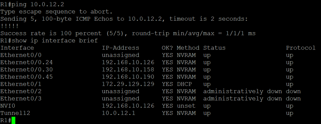
Verify the tunnel is up and operational
Ping R2 tunnel’s interface from Router R1. Using ‘show ip interface brief’ verify that the tunnel is up.

Configure EIGRP on Router R1
Using AS (Autonomous System) 1, configure EIGRP. Set the routing protocol to not auto-summarize. Advertise the sub-interfaces networks and the GRE Tunnel subnet using the wildcard mask set the limits of the advertised networks.

R1#configure terminal
R1(config)#router eigrp 1
R1(config-router)#no auto-summary
R1(config-router)#network 192.168.10.0 0.0.0.127
R1(config-router)#network 192.168.10.128 0.0.0.31
R1(config-router)#network 192.168.10.160 0.0.0.31
R1(config-router)#network 10.0.12.0 0.0.0.3

Configure EIGRP on Router R2
Using AS (Autonomous System) 1, configure EIGRP. Set the routing protocol to not auto-summarize. Advertise the sub-interfaces networks and the GRE Tunnel subnet using the wildcard mask set the limits of the advertised networks.

R2#configure terminal
R2(config)#router eigrp 1
R2(config-router)#no auto-summary
R2(config-router)#network 192.168.20.0 0.0.0.63
R2(config-router)#network 192.168.20.64 0.0.0.31
R2(config-router)#network 10.0.12.0 0.0.0.3

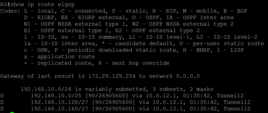
Verify that Router R2 has learned Router R1 internal networks
Using ‘show ip route eigrp’ verify that router R2 has learned the networks advertised from router R1.