Static NAT translation using a Cisco router

Network address translation (NAT) is a process used in computer networks that allows private IP addresses to be translated into a public IP address. Public IP addresses are limited and in most cases most businesses will only have one public IP address assigned to them. For this reason they need to use NAT in order to translate a private IP address into a public IP address.

Static NAT allows the router translate one-to-one translations of inside local addresses to outside global address. When using static NAT the router assigns addresses on a one-to-one basis, so you will need an equal number of public addresses as private addresses.

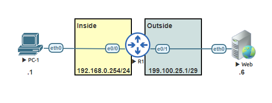
This lab is a simple Static NAT lab, that translate one private IP to one public IP address.

Task 1:
Configure the host name on both the router and switch.

Router>enable
Router#configure terminal
Router(config)#hostname R1
R1(config)#

Task 2:
Set the IP address to the inside and outside interfaces.

R1(config)#interface ethernet 0/0
R1(config-if)#ip address 192.168.0.254 255.255.255.0
R1(config-if)#no shutdown
R1(config-if)#exit
R1(config)#interface ethernet 0/1
R1(config-if)#ip address 199.100.25.1 255.255.255.248
R1(config-if)#no shutdown
R1(config-if)#exit

Task 3:
Configure the host name and assign the IP address to PC-1 . Ping the gateway to confirm the connectivity.

VPCS>  set pcname PC-1

PC-1> ip 192.168.0.1 /24 192.168.0.254
Checking for duplicate address...
PC1 : 192.168.0.1 255.255.255.0 gateway 192.168.0.254

PC-1> ping 192.168.0.254

84 bytes from 192.168.0.254 icmp_seq=1 ttl=255 time=0.480 ms
84 bytes from 192.168.0.254 icmp_seq=2 ttl=255 time=0.639 ms
84 bytes from 192.168.0.254 icmp_seq=3 ttl=255 time=0.693 ms
84 bytes from 192.168.0.254 icmp_seq=4 ttl=255 time=0.862 ms
84 bytes from 192.168.0.254 icmp_seq=5 ttl=255 time=0.658 ms

Task 4:
Configure the host name and assign the IP address to the Web server. Ping the gateway to confirm the connectivity.

VPCS> set pcname Web
Web> ip 199.100.25.6 /29 199.100.25.1
Checking for duplicate address...
PC1 : 199.100.25.6 255.255.255.248 gateway 199.100.25.1

Web> ping 199.100.25.1

84 bytes from 199.100.25.1 icmp_seq=1 ttl=255 time=0.417 ms
84 bytes from 199.100.25.1 icmp_seq=2 ttl=255 time=0.511 ms
84 bytes from 199.100.25.1 icmp_seq=3 ttl=255 time=0.528 ms
84 bytes from 199.100.25.1 icmp_seq=4 ttl=255 time=0.519 ms
84 bytes from 199.100.25.1 icmp_seq=5 ttl=255 time=0.502 ms

Task 5:
Configure the inside and outside NAT interfaces.

R1(config)#interface ethernet 0/0
R1(config-if)#ip nat inside
R1(config-if)#exit
R1(config)#interface ethernet 0/1
R1(config-if)#ip nat outside
R1(config-if)#exit

Task 6:
Configure the static NAT rule.

R1(config)#ip nat inside source static 192.168.0.1 199.100.25.1

Task 7:
Verify the NAT translation on the router.

R1#show ip nat translations
Pro Inside global      Inside local       Outside local      Outside global
--- 199.100.25.1       192.168.0.1        ---                ---

Task 8:
Ping from PC-1 to the Web server. Afterwards, return back to the router and run the command ‘show ip nat statistics’.

PC-1> ping 199.100.25.6

84 bytes from 199.100.25.6 icmp_seq=1 ttl=63 time=0.909 ms
84 bytes from 199.100.25.6 icmp_seq=2 ttl=63 time=0.841 ms
84 bytes from 199.100.25.6 icmp_seq=3 ttl=63 time=1.166 ms
84 bytes from 199.100.25.6 icmp_seq=4 ttl=63 time=0.889 ms
84 bytes from 199.100.25.6 icmp_seq=5 ttl=63 time=0.883 ms


R1#show ip nat statistics
Total active translations: 1 (1 static, 0 dynamic; 0 extended)
Peak translations: 1, occurred 01:05:01 ago
Outside interfaces:
  Ethernet0/1
Inside interfaces:
  Ethernet0/0
Hits: 0  Misses: 0
CEF Translated packets: 0, CEF Punted packets: 0
Expired translations: 0
Dynamic mappings:

Total doors: 0
Appl doors: 0
Normal doors: 0
Queued Packets: 0
R1#show ip nat statistics
Total active translations: 6 (1 static, 5 dynamic; 5 extended)
Peak translations: 6, occurred 00:00:07 ago
Outside interfaces:
  Ethernet0/1
Inside interfaces:
  Ethernet0/0
Hits: 10  Misses: 0
CEF Translated packets: 10, CEF Punted packets: 0
Expired translations: 0
Dynamic mappings:

Total doors: 0
Appl doors: 0
Normal doors: 0
Queued Packets: 0

Lab: DHCP Server with a VLSM network

IP addresses are configured statically or dynamically. This lab is a simple lab of a small business network. Two of the subnets will be dynamically assigning IP addresses and the third subnet for the servers will be statically assigned. The class A subnet 10.75.20.0/24 is divided into three variable length subnets.

Variable length subnet mask (VLSM)is when the subnet design uses more than one mask in the same network. This lab requires the workstation subnet to have a subnet mask of 255.255.255.128 which allows 126 useable IP addresses. The laboratory subnet is smaller subnet that will only require a maximum of 28 IP addresses. The subnet mask used for the laboratory subnet will be 255.255.255.224, the mask allows a total of 30 useable IP addresses.

VLAN IDSubnet NameSubnet IPMaskGateway
11Laboratory10.75.20.0255.255.255.12810.75.20.126
20Workstation10.75.20.128255.255.255.22410.75.20.158
35Server10.75.20.160255.255.255.24010.75.20.174

Task 1:
Configure the host name on both the router and switch.

Router>enable
Router#configure terminal
Router(config)#hostname R1
R1(config)#


Switch>enable
Switch#configure terminal
Switch(config)#hostname Sw1
Sw1(config)#

Task 2:
Configure the subinterfaces using 802.1q encapsulationon on the routers interface. Subinterfaces should match VLAN IDs. Assign IP addresses in each of the subinterfaces, using the identified gateway and subnet mask.

R1(config)#interface ethernet 0/0
R1(config-if)#no shutdown
R1(config-if)#interface ethernet 0/0.11
R1(config-subif)#encapsulation dot1q 11
R1(config-subif)#description vLAN-11_Laboratory
R1(config-subif)#ip address 10.75.20.126 255.255.255.128
R1(config-subif)#no shutdown
R1(config-subif)#exit
R1(config)#interface ethernet 0/0.20
R1(config-subif)#encapsulation dot1q 20
R1(config-subif)#description vLAN-20_Workstation
R1(config-subif)#ip address 10.75.20.158 255.255.255.224
R1(config-subif)#no shutdown
R1(config-subif)#exit
R1(config)#interface ethernet 0/0.35
R1(config-subif)#encapsulation dot1q 35
R1(config-subif)#description vLAN-35_Server
R1(config-subif)#ip address 10.75.20.174 255.255.255.240
R1(config-subif)#no shutdown
R1(config-subif)#exit
R1(config)#

Task 3:
Create DHCP pools on the DHCP Server router R1. Don’t forget to exclude the gateway address for both DHCP pools.

R1(config)#ip dhcp pool v11-Laboratory-Pool
R1(dhcp-config)#network 10.75.20.0 255.255.255.128
R1(dhcp-config)#default-router 10.75.20.126
R1(dhcp-config)#exit
R1(config)#ip dhcp pool v20-Workstation-Pool
R1(dhcp-config)#network 10.75.20.128 255.255.255.224
R1(dhcp-config)#default-router 10.75.20.158
R1(dhcp-config)#exit
R1(config)#ip dhcp excluded-address 10.75.20.126
R1(config)#ip dhcp excluded-address 10.75.20.158
R1(config)#end
R1#

Task 4:
Add VLANs to VLAN database on switch. Name them properly defined in the table next to the topology.

Sw1(config)#vlan 11
Sw1(config-vlan)#name vLAN-11-Laboratory
Sw1(config-vlan)#exit
Sw1(config)#vlan 20
Sw1(config-vlan)#name vLAN-20-Workstation
Sw1(config-vlan)#exit
Sw1(config)#vlan 35
Sw1(config-vlan)#name vLAN-35-Server
Sw1(config-vlan)#exit
Sw1(config)#


Task 5:
Configure the trunk from the switch to the router.

Sw1(config)#interface ethernet 3/3
Sw1(config-if)#switchport trunk encapsulation dot1q
Sw1(config-if)#switchport mode trunk
Sw1(config-if)#switchport trunk allowed vlan 11,20,35

Task 6:
Configure access ports for each of the devices and assign the proper VLAN to the respective subnet on the switch. Enable the ports to immediately go into a forwarding state.

Sw1(config)#interface range ethernet 0/1 - 2
Sw1(config-if-range)#switchport mode access
Sw1(config-if-range)#switchport access vlan 11
Sw1(config-if-range)#spanning-tree portfast
Sw1(config-if-range)#exit
Sw1(config)#interface range ethernet 1/1 - 2
Sw1(config-if-range)#switchport mode access
Sw1(config-if-range)#switchport access vlan 20
Sw1(config-if-range)#spanning-tree portfast
Sw1(config-if-range)#exit
Sw1(config)#interface range ethernet 2/1 - 2
Sw1(config-if-range)#switchport mode access
Sw1(config-if-range)#switchport access vlan 35
Sw1(config-if-range)#spanning-tree portfast
Sw1(config-if-range)#exit

Task 7:
Configure the servers with their respective host names, and Assign VPC7 the first available IP of the subnet and assign VPC8 the second available IP of the subnet. Don’t forget assign the gateway address.

VPCS> set pcname VPC7
VPC7> ip 10.75.20.161 /28 10.75.20.174
Checking for duplicate address...
PC1 : 10.75.20.161 255.255.255.240 gateway 10.75.20.174


VPCS> set pcname VPC8
VPC8> ip 10.75.20.162 /28 10.75.20.174
Checking for duplicate address...
PC1 : 10.75.20.162 255.255.255.240 gateway 10.75.20.174

Task 8:
Configure the host names of the Laboratory desktop PCs and configure them as DHCP clients. Ping the gateway to confirm the PCs connection.

VPCS> set pcname VPC3
VPC3> ip dhcp
DDORA IP 10.75.20.1/25 GW 10.75.20.126

VPC3> ping 10.75.20.126

84 bytes from 10.75.20.126 icmp_seq=1 ttl=255 time=0.566 ms
84 bytes from 10.75.20.126 icmp_seq=2 ttl=255 time=0.901 ms
84 bytes from 10.75.20.126 icmp_seq=3 ttl=255 time=1.188 ms
84 bytes from 10.75.20.126 icmp_seq=4 ttl=255 time=1.158 ms
84 bytes from 10.75.20.126 icmp_seq=5 ttl=255 time=0.947 ms

VPCS> set pcname VPC4
VPC4> ip dhcp
DDORA IP 10.75.20.2/25 GW 10.75.20.126

VPC4> ping 10.75.20.126

84 bytes from 10.75.20.126 icmp_seq=1 ttl=255 time=0.581 ms
84 bytes from 10.75.20.126 icmp_seq=2 ttl=255 time=0.952 ms
84 bytes from 10.75.20.126 icmp_seq=3 ttl=255 time=1.306 ms
84 bytes from 10.75.20.126 icmp_seq=4 ttl=255 time=0.921 ms
84 bytes from 10.75.20.126 icmp_seq=5 ttl=255 time=0.953 ms

Task 9:
Configure the host names of the Workstation Laptop PCs and configure them as DHCP clients. Ping the gateway to confirm the PCs connection.

VPCS> set pcname VPC5
VPC5> ip dhcp
DDORA IP 10.75.20.129/27 GW 10.75.20.158

VPC5> ping 10.75.20.158

84 bytes from 10.75.20.158 icmp_seq=1 ttl=255 time=0.606 ms
84 bytes from 10.75.20.158 icmp_seq=2 ttl=255 time=1.243 ms
84 bytes from 10.75.20.158 icmp_seq=3 ttl=255 time=1.294 ms
84 bytes from 10.75.20.158 icmp_seq=4 ttl=255 time=1.304 ms
84 bytes from 10.75.20.158 icmp_seq=5 ttl=255 time=1.386 ms


VPCS> set pcname VPC6
VPC6> ip dhcp
DDORA IP 10.75.20.130/27 GW 10.75.20.158

VPC6> ping 10.75.20.158

84 bytes from 10.75.20.158 icmp_seq=1 ttl=255 time=0.736 ms
84 bytes from 10.75.20.158 icmp_seq=2 ttl=255 time=1.036 ms
84 bytes from 10.75.20.158 icmp_seq=3 ttl=255 time=1.082 ms
84 bytes from 10.75.20.158 icmp_seq=4 ttl=255 time=1.138 ms
84 bytes from 10.75.20.158 icmp_seq=5 ttl=255 time=1.519 ms

Lab: OSPF Using Juniper and Cisco

Multi-area OSPF lab using two different vendors Juniper and Cisco. This lab is a good example of how basic OSPF actions are taking on Juniper routers and in comparison Cisco routers.

OSPF (Open Shortest Path First) is a routing protocol for Internet Protocol (IP) networks. OSPF is a link-state protocol. OSPF uses a shorted path first algorithm in order to build and calculate the shortest path to all known destinations.The shortest path is calculated with the use of the Dijkstra algorithm.

Task 1:
Change the hostnames on both Juniper routers.

lab@Vmx>configure
Entering configuration mode

[edit]
lab@Vmx#set system host-name R1
lab@Vmx#commit and-quit
lab@R1>


lab@Vmx>configure
Entering configuration mode

[edit]
lab@Vmx#set system host-name R2
lab@Vmx#commit and-quit
lab@R2>

Task 2:
Change the host names on both Cisco routers.

Router>enable
Router#configure terminal
Router(config)#hostname R3
R3(config)#


Router>enable
Router#configure terminal
Router(config)#hostname R4
R4(config)#

Task 3:
Assign IP address to the Juniper routers.

lab@R1>configure
Entering configuration mode

[edit]
lab@R1#set interfaces ge-0/0/3 unit 0 family inet address 192.168.12.1/24
lab@R1#set interfaces ge-0/0/2 unit 0 family inet address 192.168.13.1/24
lab@R1#commit and-quit
lab@R1>


lab@R2>configure
Entering configuration mode

[edit]
lab@R2#set interfaces ge-0/0/3 unit 0 family inet address 192.168.12.2/24
lab@R1#set interfaces ge-0/0/2 unit 0 family inet address 192.168.24.2/24
lab@R2#commit and-quit
lab@R2>

Task 4:
Assign IP address to the Cisco routers.

R3#configure terminal
R3(config)#interface ethernet 0/0
R3(config-if)#ip address 192.168.13.3 255.255.255.0
R3(config-if)#no shutdown
R3(config-if)#exit
R3(config)#interface loopback 0
R3(config-if)#ip address 3.3.3.3 255.255.255.255
R3(config-if)#no shutdown
R3(config-if)#exit


R4#configure terminal
R4(config)#interface ethernet 0/0
R4(config-if)#ip address 192.168.24.4 255.255.255.0
R4(config-if)#no shutdown
R4(config-if)#exit
R4(config)#interface loopback 0
R4(config-if)#ip address 4.4.4.4 255.255.255.255
R4(config-if)#no shutdown
R4(config-if)#exit

Task 5:
Configure OSPF on Juniper routers.

lab@R1>configure
Entering configuration mode

[edit]
lab@R1# set protocols ospf area 0.0.0.0 interface ge-0/0/0.3
lab@R1# set protocols ospf area 0.0.0.1 interface ge-0/0/0.2
lab@R1#commit and-quit


lab@R2>configure
Entering configuration mode

[edit]
lab@R2# set protocols ospf area 0.0.0.0 interface ge-0/0/0.3
lab@R2# set protocols ospf area 0.0.0.1 interface ge-0/0/0.2
lab@R1#commit and-quit

Task 6:
Configure OSPF on Cisco routers.

R3#configure terminal
R3(config)#router ospf 1
R3(config-router)#network 192.168.13.0 0.0.0.255 area 1
R3(config-router)#network 3.3.3.3 0.0.0.0 area 1
R3(config-router)#end
R3#


R4#configure terminal
R4(config)#router ospf 1
R4(config-router)#network 192.168.13.0 0.0.0.255 area 2
R4(config-router)#network 4.4.4.4 0.0.0.0 area 2
R4(config-router)#end
R4#