Lab: Router on a Stick

This is a basic lab, that will reinforce a common use of inter-VLAN routing. Most enterprise networks separate their traffic using VLANs. VLANs are virtual isolated LAN segments.

VLANs define the limits of broadcast domains in a Layer 2 network. A broadcast domain is typically bounded or enclosed by routers as they do not forward the broadcast frames. VLANs enforce a boundary, limited to the amount of devices on a particular subnet. In order to allow communication between the subnets a layer 3 device is needed, as traffic cannot pass directly to another VLAN.

Task 1:
Configure the hostname on both the router and switch.

Router>enable
Router#configure terminal
Router(config)#hostname R1
R1(config)#


Switch>enable
Switch#configure terminal
Switch(config)#hostname Sw1
Sw1(config)#

Task 2:
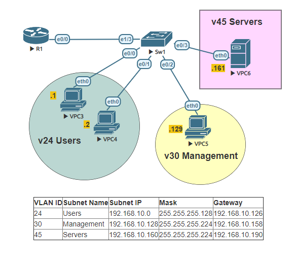
Configure the subinterfaces using 802.1q encapsulationon the routers interface. Subinterfaces should match VLAN IDs. Assign IP addresses in each of the subinterfaces, using the identified gateway and subnet mask.

R1(config)#interface Ethernet 0/0
R1(config-if)#no shutdown

*Nov 15 03:04:46.062: %LINK-3-UPDOWN: Interface Ethernet0/0, changed state to up
*Nov 15 03:04:47.066: %LINEPROTO-5-UPDOWN: Line protocol on Interface Ethernet0/0, changed state to up

R1(config-if)#interface Ethernet 0/0.24
R1(config-subif)#encapsulation dot1q 24
R1(config-subif)#ip address 192.168.10.126 255.255.255.128
R1(config-subif)#no shutdown
R1(config-subif)#exit
R1(config)#interface Ethernet 0/0.30
R1(config-subif)#encapsulation dot1q 30
R1(config-subif)#ip address 192.168.10.158 255.255.255.224
R1(config-subif)#no shutdown
R1(config-subif)#exit
R1(config)#interface Ethernet 0/0.45
R1(config-subif)#encapsulation dot1q 45
R1(config-subif)#ip address 192.168.10.190 255.255.255.224
R1(config-subif)#no shutdown
R1(config-subif)#end

Task 3:
Verify the ports are up and operational and that they have the correct IP Address assigned on each subinterface.

R1#show ip interface brief
Interface IP-Address OK? Method Status Protocol Ethernet0/0 unassigned YES unset up up Ethernet0/0.24 192.168.10.126 YES manual up up Ethernet0/0.30 192.168.10.158 YES manual up up Ethernet0/0.45 192.168.10.190 YES manual up up Ethernet0/1 unassigned YES unset administratively down down Ethernet0/2 unassigned YES unset administratively down down Ethernet0/3 unassigned YES unset administratively down down

Task 4:
Add VLANs to VLAN database on switch. Name them properly defined in the table next to the topology.

Sw1#configure terminal

Enter configuration commands, one per line.  End with CNTL/Z.
Sw1(config)#vlan 24
Sw1(config-vlan)#name Users
Sw1(config-vlan)#exit
Sw1(config)#vlan 30
Sw1(config-vlan)#name Management
Sw1(config-vlan)#exit
Sw1(config)#vlan 45
Sw1(config-vlan)#name Servers
Sw1(config-vlan)#end

Task 5:
By default trunks allow all vlans. Configure the trunk on switch and prune VLANs allowed to match sub-interfaces.

Sw1#configure terminal

Enter configuration commands, one per line.  End with CNTL/Z.

Sw1(config)#interface Ethernet 1/3
Sw1(config-if)#switchport trunk encapsulation dot1q
Sw1(config-if)#switchport mode trunk
Sw1(config-if)#switchport trunk allowed vlan 24,30,45
Sw1(config-if)#end

Task 6:
Configure access ports to match the topology on the switch.

Sw1#configure terminal

Enter configuration commands, one per line.  End with CNTL/Z.

Sw1(config)#interface Ethernet 0/0
Sw1(config-if)#switchport mode access
Sw1(config-if)#switchport access vlan 24
Sw1(config-if)#exit
Sw1(config)#interface Ethernet 0/1
Sw1(config-if)#switchport mode access
Sw1(config-if)#switchport access vlan 24
Sw1(config-if)#exit
Sw1(config)#interface Ethernet 0/2
Sw1(config-if)#switchport mode access
Sw1(config-if)#switchport access vlan 30
Sw1(config-if)#exit
Sw1(config)#interface Ethernet 0/3
Sw1(config-if)#switchport mode access
Sw1(config-if)#switchport access vlan 45
Sw1(config-if)#end

Task 7:
Verify the status of the switch ports.

Sw1#show interface status

Port      Name               Status       Vlan       Duplex  Speed Type
Et0/0                        connected    24           auto   auto unknown
Et0/1                        connected    24           auto   auto unknown
Et0/2                        connected    30           auto   auto unknown
Et0/3                        connected    45           auto   auto unknown
Et1/0                        notconnect   1            auto   auto unknown
Et1/1                        notconnect   1            auto   auto unknown
Et1/2                        notconnect   1            auto   auto unknown
Et1/3                        connected    trunk        auto   auto unknown
Sw1#

Task 8:
Configure the Virtual PCs with proper IP addresses and ping their particular gateway in order to verify that everything was configured properly. In the example below only one PC is configured, repeat the process for each PC.

VPCS> set pcname VPC3

VPC3> ip 192.168.10.1 /25 192.168.10.126
Checking for duplicate address...

PC1 : 192.168.10.1 255.255.255.128 gateway 192.168.10.126
VPC3> ping 192.168.10.126

84 bytes from 192.168.10.126 icmp_seq=1 ttl=255 time=1.308 ms
84 bytes from 192.168.10.126 icmp_seq=2 ttl=255 time=1.123 ms
84 bytes from 192.168.10.126 icmp_seq=3 ttl=255 time=1.296 ms
84 bytes from 192.168.10.126 icmp_seq=4 ttl=255 time=1.200 ms
84 bytes from 192.168.10.126 icmp_seq=5 ttl=255 time=1.287 ms

This Lab was conducted on Eve-NG. The image used was Cisco IOL. The images were obtained from Cisco VIRL. This lab can be carried out in Cisco packet tracer.

Lab: VTP Clients and Servers

The following Lab was conducted on Eve-NG. The image used was Cisco IOL. The images were obtained from Cisco VIRL.

VLAN Number VLAN Name Switch Interfaces
10Sales Sw1 e1/0  &  Sw2 e1/0
20Managers Sw1 e1/1  &  Sw2 e1/1

Task 1:
Configure the hostname on both switches.

Task 2:
Configure Sw 1 as the VTP Server, and configure Sw2 as the VTP Client. Both switches should be on the VTP domain cisco.com. 

Task 3:
Configure and verify Ethernet0/0 between Sw1 & Sw2 as a 802.1q trunk.

Task 4:
Add VLANs 10 & 20 on the VTP Server. Verify that the client switch has updates with the VLANs from the VTP Server.

Task 5:
Configure PC with corresponding IP addresses. Place the ports on corresponding VLANs as depicted in the topology. Configure the ports as access ports.

Task 6:
Ping the opposite PC of the same VLAN. 192.168.10.1 (VPC1) to  192.168.10.2 (VPC5). Repeat with the other PCs 192.168.20.1 (VPC2) to 192.168.20.2 (VPC6).