Configure Router R1
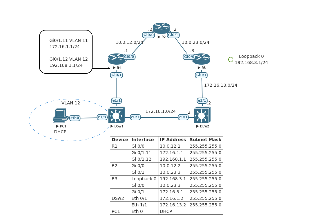
Set the hostname. Create a banner. Configure the interfaces and sub-interfaces that match the table above. Create a DHCP pool for Hosts VLAN 12.

Router>enable
Router#configure terminal
Enter configuration commands, one per line.  End with CNTL/Z.
Router(config)#hostname R1
R1(config)#no ip domain-lookup
R1(config)#banner # R1 -> Stay out of the this Router if you are not authorized #
R1(config)#interface g0/0
R1(config-if)#ip address 10.0.12.1 255.255.255.0
R1(config-if)#no shutdown
R1(config-if)#exit
R1(config)#interface g0/1
R1(config-if)#no ip address
R1(config-if)#no shutdown
R1(config)#interface g0/1.11
R1(config-subif)#encapsulation dot1q 11
R1(config-subif)#ip address 172.16.1.1 255.255.255.0
R1(config-subif)#no shutdown
R1(config-subif)#exit
R1(config)#interface g0/1.12
R1(config-subif)#encapsulation dot1q 12
R1(config-subif)#ip address 192.168.1.1 255.255.255.0
R1(config-subif)#no shutdown
R1(config-subif)#exit
R1(config)#ip dhcp pool Hosts-Vlan-12
R1(dhcp-config)#network 192.168.1.0 255.255.255.0
R1(dhcp-config)#default-router 192.168.1.1
R1(dhcp-config)#exit

Configure Router R2
Set the hostname. Create a banner. Configure the interfaces.

Router>enable
Router#configure terminal
Enter configuration commands, one per line.  End with CNTL/Z.
Router(config)#hostname R2
R2(config)#no ip domain-lookup
R2(config)#banner # R2 -> Stay out of this Router if you are not authorized #
R2(config)#interface g0/0
R2(config-if)#ip address 10.0.12.2 255.255.255.0
R2(config-if)#no shutdown
R2(config-if)#exit
R2(config)#interface g0/1
R2(config-if)#ip address 10.0.23.2 255.255.255.0
R2(config-if)#no shutdown
R2(config-if)#exit

Configure Router R3
Set the hostname. Create a banner. Configure the interfaces and the loopback 0 address.

Router>enable
Router#configure terminal
Enter configuration commands, one per line.  End with CNTL/Z.
Router(config)#hostname R3
R3(config)#no ip domain-lookup
R3(config)#banner # R3 -> Stay out of this Router if you are not authorized #
R3(config)#interface g0/0
R3(config-if)#ip address 10.0.23.3 255.255.255.0
R3(config-if)#no shutdown
R3(config-if)#interface loopback 0
R3(config-if)#ip address 192.168.3.1 255.255.255.0
R3(config-if)#no shutdown
R3(config-if)#interface g0/1
R3(config-if)#ip address 172.16.13.1 255.255.255.0
R3(config-if)#no shutdown

Configure Switch DSw1
Set the hostname. Create a banner. Create VLANs 11 & 12. Configure its uplink port as a trunk that allows only VLANs 11 & 12. Configure port E0/1 to access VLAN 11 and configure port E1/3 to access VLAN 12.

Switch>enable
Switch#configure terminal
Enter configuration commands, one per line.  End with CNTL/Z.
Switch(config)#hostname DSw1
DSw1(config)#no ip domain-lookup
DSw1(config)#banner # DSw1 -> Stay out of this switch if you are not authorized #
DSw1(config)#vlan 11
DSw1(config-vlan)#name Management-VLAN
DSw1(config-vlan)#exit
DSw1(config)#vlan 12
DSw1(config-vlan)#name Hosts-VLAN
DSw1(config-vlan)#exit
DSw1(config)#interface ethernet 1/1
DSw1(config-if)#switchport trunk encapsulation dot1q
DSw1(config-if)#switchport mode trunk
DSw1(config-if)#switchport trunk allowed vlan 11-12
DSw1(config-if)#exit
DSw1(config)#interface ethernet 1/3
DSw1(config-if)#switchport mode access
DSw1(config-if)#switchport access vlan 12
DSw1(config-if)#exit
DSw1(config)#interface ethernet 0/1
DSw1(config-if)#switchport mode access
DSw1(config-if)#switchport access vlan 11
DSw1(config-if)#no shutdown

Configure Switch DSw2
Set the hostname. Create a banner. Configure the interfaces E1/1 & E0/1 as Layer three ports with the correct IP addresses.

Switch>enable
Switch#configure terminal
Enter configuration commands, one per line.  End with CNTL/Z.
Switch(config)#hostname DSw2
DSw2(config)#no ip domain-lookup
DSw2(config)#banner # DSw2 -> Stay out of this switch if you are not authorized #
DSw2(config)#interface ethernet 0/1
DSw2(config-if)#no switchport
DSw2(config-if)#ip address 172.16.1.2 255.255.255.0
DSw2(config-if)#no shutdown
DSw2(config-if)#exit
DSw2(config)#interface ethernet 1/1
DSw2(config-if)#no switchport
DSw2(config-if)#ip address 172.16.13.2 255.255.255.0
DSw2(config-if)#no shutdown
DSw2(config-if)#exit
DSw2(config)#

Configure PC PC1
Set the hostname. Using DHCP allow the PC to retrieve an IP address. Ping its gateway to verify connectivity. Save configurations.

VPCS> set pcname PC1
PC1> ip dhcp
DDORA IP 192.168.1.2/24 GW 192.168.1.1

PC1> ping 192.168.1.1

84 bytes from 192.168.1.1 icmp_seq=1 ttl=255 time=6.099 ms
84 bytes from 192.168.1.1 icmp_seq=2 ttl=255 time=4.406 ms
84 bytes from 192.168.1.1 icmp_seq=3 ttl=255 time=2.373 ms
84 bytes from 192.168.1.1 icmp_seq=4 ttl=255 time=3.879 ms
84 bytes from 192.168.1.1 icmp_seq=5 ttl=255 time=2.407 ms

PC1> save
Saving startup configuration to startup.vpc
.  done

Implement EIGRP for IPv4
Configure classic EIGRP for IPv4 on all devices. Use Autonomous System number 10, and advertise only the connected interfaces on each device. Make sure to disable auto-summarization.

R1

R1(config)#router eigrp 10
R1(config-router)#no auto-summary
R1(config-router)#network 10.0.12.0
R1(config-router)#network 172.16.1.0
R1(config-router)#network 192.168.1.0
R1(config-router)#end

R2

R2(config)#router eigrp 10
R2(config-router)#no auto-summary
R2(config-router)#network 10.0.12.0
R2(config-router)#network 10.0.23.0
R2(config-router)#end

R3

R3(config)#router eigrp 10
R3(config-router)#no auto-summary
R3(config-router)#network 10.0.23.0
R3(config-router)#network 192.168.3.0
R3(config-router)#network 172.16.13.0
R3(config-router)#end
R3#

DSw2

DSw2(config)#router eigrp 10
DSw2(config-router)#no auto-summary
DSw2(config-router)#network 172.16.1.0
DSw2(config-router)#network 172.16.13.0
DSw2(config-router)#end
DSw2#

Verify connectivity
From DSw2 ping PC1.

DSw2#ping 192.168.1.2
Type escape sequence to abort.
Sending 5, 100-byte ICMP Echos to 192.168.1.2, timeout is 2 seconds:
!!!!!
Success rate is 100 percent (5/5), round-trip min/avg/max = 3/4/10 ms

On router R2 enter the “show ip eigrp interfaces” command.

R2#show ip eigrp interfaces
EIGRP-IPv4 Interfaces for AS(10)
                              Xmit Queue   PeerQ        Mean   Pacing Time   Multicast    Pending
Interface              Peers  Un/Reliable  Un/Reliable  SRTT   Un/Reliable   Flow Timer   Routes
Gi0/0                    1        0/0       0/0         142       0/0          704           0
Gi0/1                    1        0/0       0/0          10       0/0           50           0

Change Router R1 from Classic EIGRP to named EIGRP
Remove the router EIGRP 10 configuration from Router R1. Configure named EIGRP for IPv4 on the router. Enter into address-family configuration mode using AS 10. Configure a router-id of 1.1.1.1. Configure the network commands using wildcard bits to determine the network size.

R1(config)#no router eigrp 10
R1(config)#router eigrp EIGRP-AS10
R1(config-router)#address-family ipv4 unicast autonomous-system 10
R1(config-router-af)#eigrp router-id 1.1.1.1
R1(config-router-af)#network 10.0.12.0 0.0.0.255
*Dec 22 04:01:51.305: %DUAL-5-NBRCHANGE: EIGRP-IPv4 10: Neighbor 10.0.12.2 (GigabitEthernet0/0) is up: new adjacency
R1(config-router-af)#network 172.16.1.0 0.0.0.255
*Dec 22 04:02:33.751: %DUAL-5-NBRCHANGE: EIGRP-IPv4 10: Neighbor 172.16.1.2 (GigabitEthernet0/1.11) is up: new adjacency
R1(config-router-af)#network 192.168.1.0 0.0.0.255

On Router examine the EIGRP entries in the routing table, using the “show ip route eigrp | begin Gateway” command.

R1#show ip route eigrp | begin Gateway
Gateway of last resort is not set

10.0.0.0/8 is variably subnetted, 3 subnets, 2 masks
D 10.0.23.0/24 [90/15360] via 10.0.12.2, 00:08:44, GigabitEthernet0/0
172.16.0.0/16 is variably subnetted, 3 subnets, 2 masks
D 172.16.13.0/24 [90/20480] via 10.0.12.2, 00:08:44, GigabitEthernet0/0
D 192.168.3.0/24 [90/2575360] via 10.0.12.2, 00:08:44, GigabitEthernet0/0

Now examine the EIGRP topology table the all-links parameter in order to display all available routes. All though R1 has multiple ways to get to the 192.168.3.0/24 network only one gets moved to the routing table. EIGRP topology table is the EIGRP’s database of route information. EIGRP using the DUAL algorithm selects the best path to a particular network and then proceeds to add the best route to the routing table.

R1#show ip eigrp topology all-links
EIGRP-IPv4 VR(EIGRP-AS10) Topology Table for AS(10)/ID(1.1.1.1)
Codes: P - Passive, A - Active, U - Update, Q - Query, R - Reply,
       r - reply Status, s - sia Status

P 192.168.3.0/24, 1 successors, FD is 329646080, serno 3
        via 10.0.12.2 (329646080/328990720), GigabitEthernet0/0
        via 172.16.1.2 (459407360/458752000), GigabitEthernet0/1.11
P 172.16.13.0/24, 1 successors, FD is 2621440, serno 4
        via 10.0.12.2 (2621440/1966080), GigabitEthernet0/0
        via 172.16.1.2 (131727360/131072000), GigabitEthernet0/1.11
P 192.168.1.0/24, 1 successors, FD is 1310720, serno 6
        via Connected, GigabitEthernet0/1.12
P 172.16.1.0/24, 1 successors, FD is 1310720, serno 5
        via Connected, GigabitEthernet0/1.11
P 10.0.23.0/24, 1 successors, FD is 1966080, serno 2
        via 10.0.12.2 (1966080/1310720), GigabitEthernet0/0
        via 172.16.1.2 (132382720/131727360), GigabitEthernet0/1.11
P 10.0.12.0/24, 1 successors, FD is 1310720, serno 1
        via Connected, GigabitEthernet0/0

Leave a Reply