Lab: Configure SSH

Connecting via SSH is essential in today’s networks. Cisco devices are not automatically capable to use SSH. It has to be enabled and configured. SSH (Secure Shell) is a secure method to remote access network devices as it includes both authentication and encryption. To configure SSH you will need an IOS image that supports crypto features.

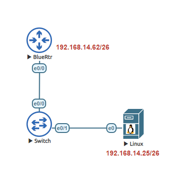
This lab is a basic SSH configuration. I will be using a Ubuntu 18.04 image as a workstation to connect to the router.

When configuring SSH on a Cisco router you will need to make sure the router has a host name. It will also need a domain name. An RSA key will need to be generated, user will need to be created on the Cisco router and finally after SSH is enabled you will need to configure the VTY lines to allow the connection to occur.

Task 1:
Configure the host name on the router.

Router>
Router>enable
Router#configure terminal
Enter configuration commands, one per line.  End with CNTL/Z.
Router(config)#hostname BlueRtr
BlueRtr(config)#

Task 2:
Configure a domain name.

BlueRtr(config)#ip domain-name joelrivera.com.local

Task 3:
Generate a RSA key. I recommend 2048 or greater when configuring the modulus bits. Make sure you use SSH version 2.

BlueRtr(config)#crypto key generate rsa
The name for the keys will be: BlueRtr.joelrivera.com.local
Choose the size of the key modulus in the range of 360 to 4096 for your
  General Purpose Keys. Choosing a key modulus greater than 512 may take
  a few minutes.

How many bits in the modulus [512]: 2048
% Generating 2048 bit RSA keys, keys will be non-exportable...
[OK] (elapsed time was 5 seconds)

BlueRtr(config)#
*Apr  5 02:57:18.367: %SSH-5-ENABLED: SSH 1.99 has been enabled
BlueRtr(config)#ip ssh version 2

Task 4:
Create a user with a password and an enable password. Make sure you use your own password and that you follow your companies security policies when creating a user account.

BlueRtr(config)#username admin secret $TrongP@$$word1234
BlueRtr(config)#enable secret cisco

Task 5:
Now that SSH is enabled we need to configure the VTY lines to allow the SSH connection through.

BlueRtr(config)#line vty 0 4
BlueRtr(config-line)#transport input ssh
BlueRtr(config-line)#login local
BlueRtr(config-line)#exit

Task 6:
Configure the ip address of the LAN connection of the router.

BlueRtr(config)#interface ethernet 0/0
BlueRtr(config-if)#ip address 192.168.14.62 255.255.255.192
BlueRtr(config-if)#no shutdown
BlueRtr(config-if)#end

Once the configuration is complete, now we need to test. I am using an Ubuntu 18.04 image. In this lab the most important part is to configure the device to be on the same network. In reality, SSH will work when connecting from an outside network so long as the device has a route to the network device and that it is not blocked from an ACL or Firewall.

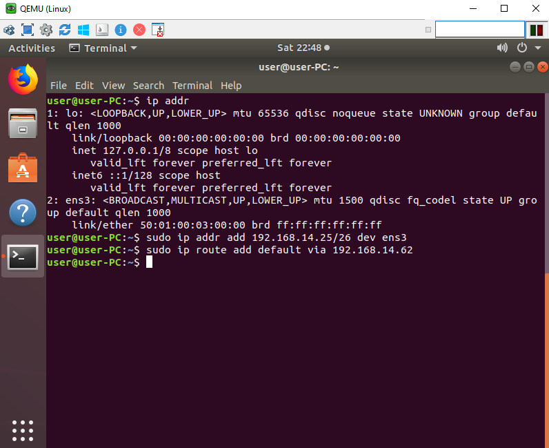
To configure a static IP address in Ubuntu 18.04, we will need to identify the physical named interface on the device. To find out the proper name type “ip addr“. Once identified in my case its ens3, Enter the following command to statically configure the IP address “sudo ip addr add 192.168.14.25/26 dev ens3“. To configure the gateway enter the following command “sudo ip route add default via 192.168.14.62“.

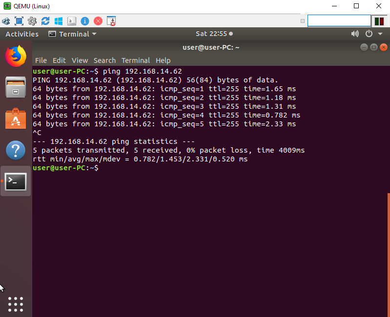
Ping the gateway to confirm the device can ping the router.

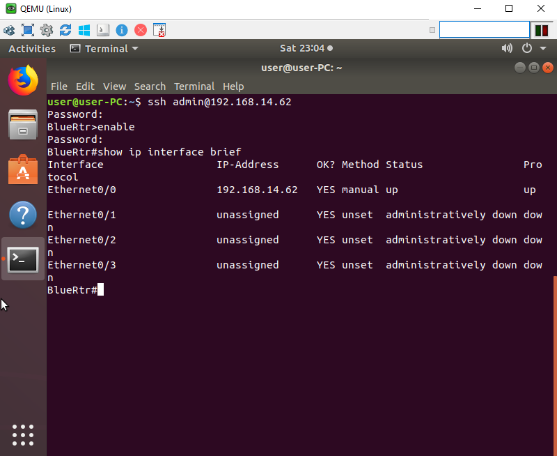
Finally let’s test the SSH connection by typing “ssh admin@192.168.14.62“. Type in the user’s password when requested, and the enable password as well. Congratulations you have configured and connected to a router via SSH.

Lab: GRE Tunnel

Generic Routing Encapsulation (GRE) is a tunneling protocol. This protocol allows the encapsulation of the network layer protocols inside other packets (packets into packets). Tunnel allows the expansion of a network that are separated in two different locations to create a point-to-point connection between the two sites.

In this lab, we will build a simple GRE Tunnel between two different sites. We are not going to encrypt the traffic, so therefore this is a non-secure remote location network.

Task 1:
Lets start with the ISP router. Configure the host name of the router and both interfaces.

Router>enable
Router#configure terminal
Router(config)#hostname ISP
ISP(config)#interface ethernet 0/0
ISP(config-if)#ip address 199.100.25.38 255.255.255.252
ISP(config-if)#no shutdown
ISP(config-if)#exit
ISP(config)#
ISP(config)#interface ethernet 0/1
ISP(config-if)#ip address 199.100.25.25 255.255.255.252
ISP(config-if)#no shutdown
ISP(config-if)#exit
ISP(config)#
ISP(config)#end
ISP#

Task 2:
Configure the HQ router. Configure the host name and both its public IP interface and the loopback 0 interface.

Router>enable
Router#configure terminal
Router(config)#hostname HQ
HQ(config)#interface ethernet 0/0
HQ(config-if)#ip address 199.100.25.37 255.255.255.252
HQ(config-if)#no shutdown
HQ(config-if)#exit
HQ(config)#
HQ(config)#interface loopback 0
HQ(config-if)#ip address
HQ(config-if)#ip address 172.16.1.1 255.255.255.255
HQ(config-if)#no shutdown
HQ(config-if)#end
HQ#

Task 3:
Configure the Branch router. Configure the host name and both its public IP interface and the loopback 0 interface.

Router>enable
Router#configure terminal
Enter configuration commands, one per line.  End with CNTL/Z.
Router(config)#hostname Branch
Branch(config)#interface ethernet 0/1
Branch(config-if)#ip address 199.100.25.26 255.255.255.252
Branch(config-if)#no shutdown
Branch(config-if)#exit
Branch(config)#interface loopback 0
Branch(config-if)#ip address 172.16.3.3 255.255.255.255
Branch(config-if)#no shutdown
Branch(config-if)#exit
Branch(config)#end
Branch#

Task 4:
In order for a tunnel to form. Both the HQ router and the Branch router will need to know how to reach each others public IP address. Add a static route on both routers to the others public ip. After both static routes have been implemented ping from the HQ router the Branch’s IP address.

Branch#configure terminal
Enter configuration commands, one per line.  End with CNTL/Z.
Branch(config)#ip route 199.100.25.37 255.255.255.255 199.100.25.25
Branch(config)#end
Branch#


HQ#configure terminal
Enter configuration commands, one per line.  End with CNTL/Z.
HQ(config)#ip route 199.100.25.26 255.255.255.255 199.100.25.38
HQ(config)#end
HQ#ping 199.100.25.26
Type escape sequence to abort.
Sending 5, 100-byte ICMP Echos to 199.100.25.26, timeout is 2 seconds:
!!!!!
Success rate is 100 percent (5/5), round-trip min/avg/max = 1/1/1 ms

Task 5:
Now we can create the tunnel interface in the HQ router. The tunnel source shall be the physical inteface towards the ISP. The destination will be the branch router public IP address.

HQ#configure terminal
Enter configuration commands, one per line.  End with CNTL/Z.
HQ(config)#interface tunnel 105
HQ(config-if)#tunnel source ethernet 0/0
HQ(config-if)#tunnel destination 199.100.25.26
HQ(config-if)#ip address 10.220.105.1 255.255.255.252
HQ(config-if)#end
HQ#

Task 6:
Create the tunnel interface in the Branch router. The tunnel source shall be the physical port that connects to the ISP. The destination will be the HQ routers public IP address. Verify the connection after completion.

Branch#configure terminal
Enter configuration commands, one per line.  End with CNTL/Z.
Branch(config)#interface tunnel 105
Branch(config-if)#tunnel source ethernet 0/1
Branch(config-if)#tunnel destination 199.100.25.37
Branch(config-if)#ip address 10.220.105.2 255.255.255.252
Branch(config-if)#exit
Branch(config)#exit
Branch#show ip interface brief
Interface                  IP-Address      OK? Method Status                Protocol
Ethernet0/0                unassigned      YES unset  administratively down down
Ethernet0/1                199.100.25.26   YES manual up                    up
Ethernet0/2                unassigned      YES unset  administratively down down
Ethernet0/3                unassigned      YES unset  administratively down down
Loopback0                  172.16.3.3      YES manual up                    up
Tunnel105                  10.220.105.2    YES manual up                    up
Branch#ping 10.220.105.1
Type escape sequence to abort.
Sending 5, 100-byte ICMP Echos to 10.220.105.1, timeout is 2 seconds:
!!!!!
Success rate is 100 percent (5/5), round-trip min/avg/max = 1/1/1 ms
Branch#show interface tunnel 105
Tunnel105 is up, line protocol is up
  Hardware is Tunnel
  Internet address is 10.220.105.2/30
  MTU 17916 bytes, BW 100 Kbit/sec, DLY 50000 usec,
     reliability 255/255, txload 1/255, rxload 1/255
  Encapsulation TUNNEL, loopback not set
  Keepalive not set
  Tunnel linestate evaluation up
  Tunnel source 199.100.25.26 (Ethernet0/1), destination 199.100.25.37
   Tunnel Subblocks:
      src-track:
         Tunnel105 source tracking subblock associated with Ethernet0/1
          Set of tunnels with source Ethernet0/1, 1 member (includes iterators), on interface 
  Tunnel protocol/transport GRE/IP
    Key disabled, sequencing disabled
    Checksumming of packets disabled
  Tunnel TTL 255, Fast tunneling enabled
  Tunnel transport MTU 1476 bytes
  Tunnel transmit bandwidth 8000 (kbps)
  Tunnel receive bandwidth 8000 (kbps)
  Last input 00:22:20, output 00:01:02, output hang never
  Last clearing of "show interface" counters 00:25:21
  Input queue: 0/75/0/0 (size/max/drops/flushes); Total output drops: 0
  Queueing strategy: fifo
  Output queue: 0/0 (size/max)
  5 minute input rate 0 bits/sec, 0 packets/sec
  5 minute output rate 0 bits/sec, 0 packets/sec
     5 packets input, 620 bytes, 0 no buffer
     Received 0 broadcasts (0 IP multicasts)
     0 runts, 0 giants, 0 throttles
     0 input errors, 0 CRC, 0 frame, 0 overrun, 0 ignored, 0 abort
     14 packets output, 1304 bytes, 0 underruns
     0 output errors, 0 collisions, 0 interface resets
     0 unknown protocol drops
     0 output buffer failures, 0 output buffers swapped out

Task 7:
Now lets use a Dynamic routing protocol, in this lab I am going to use EIGRP. With the routing protocol configured we can have the HQ router and the Branch router learn about each other’s loopback address or in another instance the LANs IP address of the site. Verify after the configuration connectivity to the HQs Loopback from the Branch router.

HQ#configure terminal
Enter configuration commands, one per line.  End with CNTL/Z.
HQ(config)#router eigrp 1
HQ(config-router)#no auto-summary
HQ(config-router)#network 172.16.1.1 0.0.0.0
HQ(config-router)#network 10.220.105.0 0.0.0.3
HQ(config-router)#end
HQ#

Branch(config)#router eigrp 1
Branch(config-router)#no auto-summary
Branch(config-router)#network 172.16.3.3 0.0.0.0
Branch(config-router)#network 10.220.105.0 0.0.0.3
Branch(config-router)#end
Branch#

Branch#ping 172.16.1.1
Type escape sequence to abort.
Sending 5, 100-byte ICMP Echos to 172.16.1.1, timeout is 2 seconds:
!!!!!
Success rate is 100 percent (5/5), round-trip min/avg/max = 1/1/1 ms

Lab: Using NAT Overload (PAT) – Using EVE-NG connect to Internet

Different than Static NAT, PAT (Port Address Translation) allows internal IPs to be translated into one IP via Port numbers. This allows a network to support many hosts while conserving public IP addresses. The router keeps a NAT table entry for every unique combination of the private IP addresses and port, with translation to the global address and a unique port number.

This lab is divided into two parts. First connecting a Cisco router to the NAT network which allows a connection to the outside (Internet). Second is using NAT overload also known as PAT to connect multiple devices from your LAN to an outside IP.

Part 1:
This is related to EVE-NG. To test the connection of the router with multiple hosts. We want to first create a connection to the internet. This will allow a more realistic lab as this is how Cisco router will usually connect to an internet connection.

1-A: Once you are in the lab screen, Right click to add a new object and select network.

1-B: In the Drop down menu, select the NAT option and then click on the save button.

1-C: Add a new object (Node), a Cisco router. Link the router to the network connection that was previously created.

1-D: Once the router powers up enter the global configuration mode. Change the host name of the router. Then enter interface configuration mode to the corresponding port that is connected to the Network object created. Once in the interface configuration mode assign the ip address to dhcp.

Router>enable
Router# configure terminal
Router(config)#hostname R1
R1(config)#interface ethernet 0/0
R1(config-if)#ip address dhcp

1-E: After an IP address has been assigned from the DHCP server. Proceed to exit the configuration mode and ping 8.8.8.8, which is Google’s DNS server address. If the ping is successful, proceed to global configuration mode again and a DNS server IP. You can use your networks own DNS or add 8.8.8.8 by typing ‘ip name-server 8.8.8.8’. Exit the global configuration mode and ping using a URL (Uniform Resource Locator). If successful you are ready to proceed to the lab.

R1#ping 8.8.8.8
Type escape sequence to abort.
Sending 5, 100-byte ICMP Echos to 8.8.8.8, timeout is 2 seconds:
!!!!!
Success rate is 100 percent (5/5), round-trip min/avg/max = 11/13/18 ms
R1#configure terminal
Enter configuration commands, one per line.  End with CNTL/Z.
R1(config)#ip name
R1(config)#ip name-server 8.8.8.8
R1(config)#exit
R1#ping www.joelrivera.com
Translating "www.joelrivera.com"...domain server (8.8.8.8) [OK]

Translating "www.joelrivera.com"...domain server (8.8.8.8) [OK]

Translating "www.joelrivera.com"...domain server (8.8.8.8) [OK]

Type escape sequence to abort.
Sending 5, 100-byte ICMP Echos to 155.138.209.62, timeout is 2 seconds:
!!!!!

Now to the lab

Subnet IPMaskGateway
192.168.113.0255.255.255.0192.168.113.254

Task 1: Configure the LAN connection.

R1#configure terminal
Enter configuration commands, one per line.  End with CNTL/Z.
R1(config)#interface ethernet 0/1
R1(config-if)#ip address 192.168.113.254 255.255.255.0
R1(config-if)# no shutdown

Task 2: Define the inside and outside interfaces on R1.

R1(config)#interface ethernet 0/1
R1(config-if)#ip nat inside
R1(config-if)#exit
R1(config)#interface ethernet 0/0
R1(config-if)#ip nat outside
R1(config-if)#exit

Task 3: Define the access list that includes the IP addresses from the inside interface.

R1(config)#access-list 10 permit 192.168.113.0 0.0.0.255

Task 4: Enable NAT and refer to the ACL created in the previous step and the outside interface.

R1(config)#ip nat inside source list 10 interface Ethernet0/0 overload

Task 5: Assign an IP address to virtual PC. Ping the google’s DNS IP address.

VPCS> ip 192.168.113.1 /24 192.168.113.254

VPCS> ping 8.8.8.8

84 bytes from 8.8.8.8 icmp_seq=1 ttl=51 time=20.990 ms
84 bytes from 8.8.8.8 icmp_seq=2 ttl=51 time=16.394 ms
84 bytes from 8.8.8.8 icmp_seq=3 ttl=51 time=16.834 ms
84 bytes from 8.8.8.8 icmp_seq=4 ttl=51 time=13.980 ms
84 bytes from 8.8.8.8 icmp_seq=5 ttl=51 time=13.271 ms

Task 6: Assign a DNS to the PC, and ping a web URL.

VPCS> ip dns 8.8.8.8

VPCS> ping www.yahoo.com
www.yahoo.com resolved to atsv2-fp-shed.wg1.b.yahoo.com(98.138.219.231)

84 bytes from 98.138.219.231 icmp_seq=1 ttl=50 time=41.102 ms
84 bytes from 98.138.219.231 icmp_seq=2 ttl=50 time=45.928 ms
84 bytes from 98.138.219.231 icmp_seq=3 ttl=50 time=39.901 ms
84 bytes from 98.138.219.231 icmp_seq=4 ttl=50 time=41.942 ms
84 bytes from 98.138.219.231 icmp_seq=5 ttl=50 time=46.653 ms

Static NAT translation using a Cisco router

Network address translation (NAT) is a process used in computer networks that allows private IP addresses to be translated into a public IP address. Public IP addresses are limited and in most cases most businesses will only have one public IP address assigned to them. For this reason they need to use NAT in order to translate a private IP address into a public IP address.

Static NAT allows the router translate one-to-one translations of inside local addresses to outside global address. When using static NAT the router assigns addresses on a one-to-one basis, so you will need an equal number of public addresses as private addresses.

This lab is a simple Static NAT lab, that translate one private IP to one public IP address.

Task 1:
Configure the host name on both the router and switch.

Router>enable
Router#configure terminal
Router(config)#hostname R1
R1(config)#

Task 2:
Set the IP address to the inside and outside interfaces.

R1(config)#interface ethernet 0/0
R1(config-if)#ip address 192.168.0.254 255.255.255.0
R1(config-if)#no shutdown
R1(config-if)#exit
R1(config)#interface ethernet 0/1
R1(config-if)#ip address 199.100.25.1 255.255.255.248
R1(config-if)#no shutdown
R1(config-if)#exit

Task 3:
Configure the host name and assign the IP address to PC-1 . Ping the gateway to confirm the connectivity.

VPCS>  set pcname PC-1

PC-1> ip 192.168.0.1 /24 192.168.0.254
Checking for duplicate address...
PC1 : 192.168.0.1 255.255.255.0 gateway 192.168.0.254

PC-1> ping 192.168.0.254

84 bytes from 192.168.0.254 icmp_seq=1 ttl=255 time=0.480 ms
84 bytes from 192.168.0.254 icmp_seq=2 ttl=255 time=0.639 ms
84 bytes from 192.168.0.254 icmp_seq=3 ttl=255 time=0.693 ms
84 bytes from 192.168.0.254 icmp_seq=4 ttl=255 time=0.862 ms
84 bytes from 192.168.0.254 icmp_seq=5 ttl=255 time=0.658 ms

Task 4:
Configure the host name and assign the IP address to the Web server. Ping the gateway to confirm the connectivity.

VPCS> set pcname Web
Web> ip 199.100.25.6 /29 199.100.25.1
Checking for duplicate address...
PC1 : 199.100.25.6 255.255.255.248 gateway 199.100.25.1

Web> ping 199.100.25.1

84 bytes from 199.100.25.1 icmp_seq=1 ttl=255 time=0.417 ms
84 bytes from 199.100.25.1 icmp_seq=2 ttl=255 time=0.511 ms
84 bytes from 199.100.25.1 icmp_seq=3 ttl=255 time=0.528 ms
84 bytes from 199.100.25.1 icmp_seq=4 ttl=255 time=0.519 ms
84 bytes from 199.100.25.1 icmp_seq=5 ttl=255 time=0.502 ms

Task 5:
Configure the inside and outside NAT interfaces.

R1(config)#interface ethernet 0/0
R1(config-if)#ip nat inside
R1(config-if)#exit
R1(config)#interface ethernet 0/1
R1(config-if)#ip nat outside
R1(config-if)#exit

Task 6:
Configure the static NAT rule.

R1(config)#ip nat inside source static 192.168.0.1 199.100.25.1

Task 7:
Verify the NAT translation on the router.

R1#show ip nat translations
Pro Inside global      Inside local       Outside local      Outside global
--- 199.100.25.1       192.168.0.1        ---                ---

Task 8:
Ping from PC-1 to the Web server. Afterwards, return back to the router and run the command ‘show ip nat statistics’.

PC-1> ping 199.100.25.6

84 bytes from 199.100.25.6 icmp_seq=1 ttl=63 time=0.909 ms
84 bytes from 199.100.25.6 icmp_seq=2 ttl=63 time=0.841 ms
84 bytes from 199.100.25.6 icmp_seq=3 ttl=63 time=1.166 ms
84 bytes from 199.100.25.6 icmp_seq=4 ttl=63 time=0.889 ms
84 bytes from 199.100.25.6 icmp_seq=5 ttl=63 time=0.883 ms


R1#show ip nat statistics
Total active translations: 1 (1 static, 0 dynamic; 0 extended)
Peak translations: 1, occurred 01:05:01 ago
Outside interfaces:
  Ethernet0/1
Inside interfaces:
  Ethernet0/0
Hits: 0  Misses: 0
CEF Translated packets: 0, CEF Punted packets: 0
Expired translations: 0
Dynamic mappings:

Total doors: 0
Appl doors: 0
Normal doors: 0
Queued Packets: 0
R1#show ip nat statistics
Total active translations: 6 (1 static, 5 dynamic; 5 extended)
Peak translations: 6, occurred 00:00:07 ago
Outside interfaces:
  Ethernet0/1
Inside interfaces:
  Ethernet0/0
Hits: 10  Misses: 0
CEF Translated packets: 10, CEF Punted packets: 0
Expired translations: 0
Dynamic mappings:

Total doors: 0
Appl doors: 0
Normal doors: 0
Queued Packets: 0

Lab: DHCP Server with a VLSM network

IP addresses are configured statically or dynamically. This lab is a simple lab of a small business network. Two of the subnets will be dynamically assigning IP addresses and the third subnet for the servers will be statically assigned. The class A subnet 10.75.20.0/24 is divided into three variable length subnets.

Variable length subnet mask (VLSM)is when the subnet design uses more than one mask in the same network. This lab requires the workstation subnet to have a subnet mask of 255.255.255.128 which allows 126 useable IP addresses. The laboratory subnet is smaller subnet that will only require a maximum of 28 IP addresses. The subnet mask used for the laboratory subnet will be 255.255.255.224, the mask allows a total of 30 useable IP addresses.

VLAN IDSubnet NameSubnet IPMaskGateway
11Laboratory10.75.20.0255.255.255.12810.75.20.126
20Workstation10.75.20.128255.255.255.22410.75.20.158
35Server10.75.20.160255.255.255.24010.75.20.174

Task 1:
Configure the host name on both the router and switch.

Router>enable
Router#configure terminal
Router(config)#hostname R1
R1(config)#


Switch>enable
Switch#configure terminal
Switch(config)#hostname Sw1
Sw1(config)#

Task 2:
Configure the subinterfaces using 802.1q encapsulationon on the routers interface. Subinterfaces should match VLAN IDs. Assign IP addresses in each of the subinterfaces, using the identified gateway and subnet mask.

R1(config)#interface ethernet 0/0
R1(config-if)#no shutdown
R1(config-if)#interface ethernet 0/0.11
R1(config-subif)#encapsulation dot1q 11
R1(config-subif)#description vLAN-11_Laboratory
R1(config-subif)#ip address 10.75.20.126 255.255.255.128
R1(config-subif)#no shutdown
R1(config-subif)#exit
R1(config)#interface ethernet 0/0.20
R1(config-subif)#encapsulation dot1q 20
R1(config-subif)#description vLAN-20_Workstation
R1(config-subif)#ip address 10.75.20.158 255.255.255.224
R1(config-subif)#no shutdown
R1(config-subif)#exit
R1(config)#interface ethernet 0/0.35
R1(config-subif)#encapsulation dot1q 35
R1(config-subif)#description vLAN-35_Server
R1(config-subif)#ip address 10.75.20.174 255.255.255.240
R1(config-subif)#no shutdown
R1(config-subif)#exit
R1(config)#

Task 3:
Create DHCP pools on the DHCP Server router R1. Don’t forget to exclude the gateway address for both DHCP pools.

R1(config)#ip dhcp pool v11-Laboratory-Pool
R1(dhcp-config)#network 10.75.20.0 255.255.255.128
R1(dhcp-config)#default-router 10.75.20.126
R1(dhcp-config)#exit
R1(config)#ip dhcp pool v20-Workstation-Pool
R1(dhcp-config)#network 10.75.20.128 255.255.255.224
R1(dhcp-config)#default-router 10.75.20.158
R1(dhcp-config)#exit
R1(config)#ip dhcp excluded-address 10.75.20.126
R1(config)#ip dhcp excluded-address 10.75.20.158
R1(config)#end
R1#

Task 4:
Add VLANs to VLAN database on switch. Name them properly defined in the table next to the topology.

Sw1(config)#vlan 11
Sw1(config-vlan)#name vLAN-11-Laboratory
Sw1(config-vlan)#exit
Sw1(config)#vlan 20
Sw1(config-vlan)#name vLAN-20-Workstation
Sw1(config-vlan)#exit
Sw1(config)#vlan 35
Sw1(config-vlan)#name vLAN-35-Server
Sw1(config-vlan)#exit
Sw1(config)#


Task 5:
Configure the trunk from the switch to the router.

Sw1(config)#interface ethernet 3/3
Sw1(config-if)#switchport trunk encapsulation dot1q
Sw1(config-if)#switchport mode trunk
Sw1(config-if)#switchport trunk allowed vlan 11,20,35

Task 6:
Configure access ports for each of the devices and assign the proper VLAN to the respective subnet on the switch. Enable the ports to immediately go into a forwarding state.

Sw1(config)#interface range ethernet 0/1 - 2
Sw1(config-if-range)#switchport mode access
Sw1(config-if-range)#switchport access vlan 11
Sw1(config-if-range)#spanning-tree portfast
Sw1(config-if-range)#exit
Sw1(config)#interface range ethernet 1/1 - 2
Sw1(config-if-range)#switchport mode access
Sw1(config-if-range)#switchport access vlan 20
Sw1(config-if-range)#spanning-tree portfast
Sw1(config-if-range)#exit
Sw1(config)#interface range ethernet 2/1 - 2
Sw1(config-if-range)#switchport mode access
Sw1(config-if-range)#switchport access vlan 35
Sw1(config-if-range)#spanning-tree portfast
Sw1(config-if-range)#exit

Task 7:
Configure the servers with their respective host names, and Assign VPC7 the first available IP of the subnet and assign VPC8 the second available IP of the subnet. Don’t forget assign the gateway address.

VPCS> set pcname VPC7
VPC7> ip 10.75.20.161 /28 10.75.20.174
Checking for duplicate address...
PC1 : 10.75.20.161 255.255.255.240 gateway 10.75.20.174


VPCS> set pcname VPC8
VPC8> ip 10.75.20.162 /28 10.75.20.174
Checking for duplicate address...
PC1 : 10.75.20.162 255.255.255.240 gateway 10.75.20.174

Task 8:
Configure the host names of the Laboratory desktop PCs and configure them as DHCP clients. Ping the gateway to confirm the PCs connection.

VPCS> set pcname VPC3
VPC3> ip dhcp
DDORA IP 10.75.20.1/25 GW 10.75.20.126

VPC3> ping 10.75.20.126

84 bytes from 10.75.20.126 icmp_seq=1 ttl=255 time=0.566 ms
84 bytes from 10.75.20.126 icmp_seq=2 ttl=255 time=0.901 ms
84 bytes from 10.75.20.126 icmp_seq=3 ttl=255 time=1.188 ms
84 bytes from 10.75.20.126 icmp_seq=4 ttl=255 time=1.158 ms
84 bytes from 10.75.20.126 icmp_seq=5 ttl=255 time=0.947 ms

VPCS> set pcname VPC4
VPC4> ip dhcp
DDORA IP 10.75.20.2/25 GW 10.75.20.126

VPC4> ping 10.75.20.126

84 bytes from 10.75.20.126 icmp_seq=1 ttl=255 time=0.581 ms
84 bytes from 10.75.20.126 icmp_seq=2 ttl=255 time=0.952 ms
84 bytes from 10.75.20.126 icmp_seq=3 ttl=255 time=1.306 ms
84 bytes from 10.75.20.126 icmp_seq=4 ttl=255 time=0.921 ms
84 bytes from 10.75.20.126 icmp_seq=5 ttl=255 time=0.953 ms

Task 9:
Configure the host names of the Workstation Laptop PCs and configure them as DHCP clients. Ping the gateway to confirm the PCs connection.

VPCS> set pcname VPC5
VPC5> ip dhcp
DDORA IP 10.75.20.129/27 GW 10.75.20.158

VPC5> ping 10.75.20.158

84 bytes from 10.75.20.158 icmp_seq=1 ttl=255 time=0.606 ms
84 bytes from 10.75.20.158 icmp_seq=2 ttl=255 time=1.243 ms
84 bytes from 10.75.20.158 icmp_seq=3 ttl=255 time=1.294 ms
84 bytes from 10.75.20.158 icmp_seq=4 ttl=255 time=1.304 ms
84 bytes from 10.75.20.158 icmp_seq=5 ttl=255 time=1.386 ms


VPCS> set pcname VPC6
VPC6> ip dhcp
DDORA IP 10.75.20.130/27 GW 10.75.20.158

VPC6> ping 10.75.20.158

84 bytes from 10.75.20.158 icmp_seq=1 ttl=255 time=0.736 ms
84 bytes from 10.75.20.158 icmp_seq=2 ttl=255 time=1.036 ms
84 bytes from 10.75.20.158 icmp_seq=3 ttl=255 time=1.082 ms
84 bytes from 10.75.20.158 icmp_seq=4 ttl=255 time=1.138 ms
84 bytes from 10.75.20.158 icmp_seq=5 ttl=255 time=1.519 ms

Lab: OSPF Using Juniper and Cisco

Multi-area OSPF lab using two different vendors Juniper and Cisco. This lab is a good example of how basic OSPF actions are taking on Juniper routers and in comparison Cisco routers.

OSPF (Open Shortest Path First) is a routing protocol for Internet Protocol (IP) networks. OSPF is a link-state protocol. OSPF uses a shorted path first algorithm in order to build and calculate the shortest path to all known destinations.The shortest path is calculated with the use of the Dijkstra algorithm.

Task 1:
Change the hostnames on both Juniper routers.

lab@Vmx>configure
Entering configuration mode

[edit]
lab@Vmx#set system host-name R1
lab@Vmx#commit and-quit
lab@R1>


lab@Vmx>configure
Entering configuration mode

[edit]
lab@Vmx#set system host-name R2
lab@Vmx#commit and-quit
lab@R2>

Task 2:
Change the host names on both Cisco routers.

Router>enable
Router#configure terminal
Router(config)#hostname R3
R3(config)#


Router>enable
Router#configure terminal
Router(config)#hostname R4
R4(config)#

Task 3:
Assign IP address to the Juniper routers.

lab@R1>configure
Entering configuration mode

[edit]
lab@R1#set interfaces ge-0/0/3 unit 0 family inet address 192.168.12.1/24
lab@R1#set interfaces ge-0/0/2 unit 0 family inet address 192.168.13.1/24
lab@R1#commit and-quit
lab@R1>


lab@R2>configure
Entering configuration mode

[edit]
lab@R2#set interfaces ge-0/0/3 unit 0 family inet address 192.168.12.2/24
lab@R1#set interfaces ge-0/0/2 unit 0 family inet address 192.168.24.2/24
lab@R2#commit and-quit
lab@R2>

Task 4:
Assign IP address to the Cisco routers.

R3#configure terminal
R3(config)#interface ethernet 0/0
R3(config-if)#ip address 192.168.13.3 255.255.255.0
R3(config-if)#no shutdown
R3(config-if)#exit
R3(config)#interface loopback 0
R3(config-if)#ip address 3.3.3.3 255.255.255.255
R3(config-if)#no shutdown
R3(config-if)#exit


R4#configure terminal
R4(config)#interface ethernet 0/0
R4(config-if)#ip address 192.168.24.4 255.255.255.0
R4(config-if)#no shutdown
R4(config-if)#exit
R4(config)#interface loopback 0
R4(config-if)#ip address 4.4.4.4 255.255.255.255
R4(config-if)#no shutdown
R4(config-if)#exit

Task 5:
Configure OSPF on Juniper routers.

lab@R1>configure
Entering configuration mode

[edit]
lab@R1# set protocols ospf area 0.0.0.0 interface ge-0/0/0.3
lab@R1# set protocols ospf area 0.0.0.1 interface ge-0/0/0.2
lab@R1#commit and-quit


lab@R2>configure
Entering configuration mode

[edit]
lab@R2# set protocols ospf area 0.0.0.0 interface ge-0/0/0.3
lab@R2# set protocols ospf area 0.0.0.1 interface ge-0/0/0.2
lab@R1#commit and-quit

Task 6:
Configure OSPF on Cisco routers.

R3#configure terminal
R3(config)#router ospf 1
R3(config-router)#network 192.168.13.0 0.0.0.255 area 1
R3(config-router)#network 3.3.3.3 0.0.0.0 area 1
R3(config-router)#end
R3#


R4#configure terminal
R4(config)#router ospf 1
R4(config-router)#network 192.168.13.0 0.0.0.255 area 2
R4(config-router)#network 4.4.4.4 0.0.0.0 area 2
R4(config-router)#end
R4#

Lab: Router on a Stick

This is a basic lab, that will reinforce a common use of inter-VLAN routing. Most enterprise networks separate their traffic using VLANs. VLANs are virtual isolated LAN segments.

VLANs define the limits of broadcast domains in a Layer 2 network. A broadcast domain is typically bounded or enclosed by routers as they do not forward the broadcast frames. VLANs enforce a boundary, limited to the amount of devices on a particular subnet. In order to allow communication between the subnets a layer 3 device is needed, as traffic cannot pass directly to another VLAN.

Task 1:
Configure the hostname on both the router and switch.

Router>enable
Router#configure terminal
Router(config)#hostname R1
R1(config)#


Switch>enable
Switch#configure terminal
Switch(config)#hostname Sw1
Sw1(config)#

Task 2:
Configure the subinterfaces using 802.1q encapsulationon the routers interface. Subinterfaces should match VLAN IDs. Assign IP addresses in each of the subinterfaces, using the identified gateway and subnet mask.

R1(config)#interface Ethernet 0/0
R1(config-if)#no shutdown

*Nov 15 03:04:46.062: %LINK-3-UPDOWN: Interface Ethernet0/0, changed state to up
*Nov 15 03:04:47.066: %LINEPROTO-5-UPDOWN: Line protocol on Interface Ethernet0/0, changed state to up

R1(config-if)#interface Ethernet 0/0.24
R1(config-subif)#encapsulation dot1q 24
R1(config-subif)#ip address 192.168.10.126 255.255.255.128
R1(config-subif)#no shutdown
R1(config-subif)#exit
R1(config)#interface Ethernet 0/0.30
R1(config-subif)#encapsulation dot1q 30
R1(config-subif)#ip address 192.168.10.158 255.255.255.224
R1(config-subif)#no shutdown
R1(config-subif)#exit
R1(config)#interface Ethernet 0/0.45
R1(config-subif)#encapsulation dot1q 45
R1(config-subif)#ip address 192.168.10.190 255.255.255.224
R1(config-subif)#no shutdown
R1(config-subif)#end

Task 3:
Verify the ports are up and operational and that they have the correct IP Address assigned on each subinterface.

R1#show ip interface brief
Interface IP-Address OK? Method Status Protocol Ethernet0/0 unassigned YES unset up up Ethernet0/0.24 192.168.10.126 YES manual up up Ethernet0/0.30 192.168.10.158 YES manual up up Ethernet0/0.45 192.168.10.190 YES manual up up Ethernet0/1 unassigned YES unset administratively down down Ethernet0/2 unassigned YES unset administratively down down Ethernet0/3 unassigned YES unset administratively down down

Task 4:
Add VLANs to VLAN database on switch. Name them properly defined in the table next to the topology.

Sw1#configure terminal

Enter configuration commands, one per line.  End with CNTL/Z.
Sw1(config)#vlan 24
Sw1(config-vlan)#name Users
Sw1(config-vlan)#exit
Sw1(config)#vlan 30
Sw1(config-vlan)#name Management
Sw1(config-vlan)#exit
Sw1(config)#vlan 45
Sw1(config-vlan)#name Servers
Sw1(config-vlan)#end

Task 5:
By default trunks allow all vlans. Configure the trunk on switch and prune VLANs allowed to match sub-interfaces.

Sw1#configure terminal

Enter configuration commands, one per line.  End with CNTL/Z.

Sw1(config)#interface Ethernet 1/3
Sw1(config-if)#switchport trunk encapsulation dot1q
Sw1(config-if)#switchport mode trunk
Sw1(config-if)#switchport trunk allowed vlan 24,30,45
Sw1(config-if)#end

Task 6:
Configure access ports to match the topology on the switch.

Sw1#configure terminal

Enter configuration commands, one per line.  End with CNTL/Z.

Sw1(config)#interface Ethernet 0/0
Sw1(config-if)#switchport mode access
Sw1(config-if)#switchport access vlan 24
Sw1(config-if)#exit
Sw1(config)#interface Ethernet 0/1
Sw1(config-if)#switchport mode access
Sw1(config-if)#switchport access vlan 24
Sw1(config-if)#exit
Sw1(config)#interface Ethernet 0/2
Sw1(config-if)#switchport mode access
Sw1(config-if)#switchport access vlan 30
Sw1(config-if)#exit
Sw1(config)#interface Ethernet 0/3
Sw1(config-if)#switchport mode access
Sw1(config-if)#switchport access vlan 45
Sw1(config-if)#end

Task 7:
Verify the status of the switch ports.

Sw1#show interface status

Port      Name               Status       Vlan       Duplex  Speed Type
Et0/0                        connected    24           auto   auto unknown
Et0/1                        connected    24           auto   auto unknown
Et0/2                        connected    30           auto   auto unknown
Et0/3                        connected    45           auto   auto unknown
Et1/0                        notconnect   1            auto   auto unknown
Et1/1                        notconnect   1            auto   auto unknown
Et1/2                        notconnect   1            auto   auto unknown
Et1/3                        connected    trunk        auto   auto unknown
Sw1#

Task 8:
Configure the Virtual PCs with proper IP addresses and ping their particular gateway in order to verify that everything was configured properly. In the example below only one PC is configured, repeat the process for each PC.

VPCS> set pcname VPC3

VPC3> ip 192.168.10.1 /25 192.168.10.126
Checking for duplicate address...

PC1 : 192.168.10.1 255.255.255.128 gateway 192.168.10.126
VPC3> ping 192.168.10.126

84 bytes from 192.168.10.126 icmp_seq=1 ttl=255 time=1.308 ms
84 bytes from 192.168.10.126 icmp_seq=2 ttl=255 time=1.123 ms
84 bytes from 192.168.10.126 icmp_seq=3 ttl=255 time=1.296 ms
84 bytes from 192.168.10.126 icmp_seq=4 ttl=255 time=1.200 ms
84 bytes from 192.168.10.126 icmp_seq=5 ttl=255 time=1.287 ms

This Lab was conducted on Eve-NG. The image used was Cisco IOL. The images were obtained from Cisco VIRL. This lab can be carried out in Cisco packet tracer.

Lab: VTP Clients and Servers

The following Lab was conducted on Eve-NG. The image used was Cisco IOL. The images were obtained from Cisco VIRL.

VLAN Number VLAN Name Switch Interfaces
10Sales Sw1 e1/0  &  Sw2 e1/0
20Managers Sw1 e1/1  &  Sw2 e1/1

Task 1:
Configure the hostname on both switches.

Task 2:
Configure Sw 1 as the VTP Server, and configure Sw2 as the VTP Client. Both switches should be on the VTP domain cisco.com. 

Task 3:
Configure and verify Ethernet0/0 between Sw1 & Sw2 as a 802.1q trunk.

Task 4:
Add VLANs 10 & 20 on the VTP Server. Verify that the client switch has updates with the VLANs from the VTP Server.

Task 5:
Configure PC with corresponding IP addresses. Place the ports on corresponding VLANs as depicted in the topology. Configure the ports as access ports.

Task 6:
Ping the opposite PC of the same VLAN. 192.168.10.1 (VPC1) to  192.168.10.2 (VPC5). Repeat with the other PCs 192.168.20.1 (VPC2) to 192.168.20.2 (VPC6). 

Cisco

I am a network engineer by trade. Most of my work over the years has been in Cisco IOS (Internetwork Operating System) network environment. My experience started out when in 2010 I joined the US Army. The MOS (Military Occupation Specialty) I chose 25N (Nodal network systems operator-maintainer) and thus began my career as a network engineer.

I wish to present things that I have learned over the years here on my site to share the knowledge and also as a way to look up.